F-459-R1
2-1
Chapter 2
Tires, Brakes and Drivetrain
Floor Plate
NOTE
This panel provides access to the accelerator assembly
which is mounted to the underside of the floor plate. The
master cylinder, service brake pedal and linkage are
mounted within the frame well, easily accessible when
the floor plate has been removed.
Floor Plate Removal and Assembly
1. Thoroughly clean the floor area using a vacuum.
2.
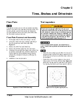
Lift up the rubber floor mat, carefully separating it
from the accelerator and brake pedal. See
Figure 2-1.
3.
Remove the M10 floor plate fasteners.
4.
Remove the left floor plate from the truck frame.
5.
Carefully lift up the right floor plate a few inches. The
accelerator pedal assembly will still be attached to
the floor plate by the accelerator wiring harness.
Unhook the accelerator harness and lift away the
floor plate.
6.
Assemble in reverse procedure.
Figure 2-1 Floor Plate Assembly
Tire Inspection
WARNING
IMPORTANT
It is recommended to replace worn front tires in
pairs. Careful driving habits add additional miles to
tire life.
NOTE
• Check the drive wheel lug nuts after 2 to 5 hours of
operation when new lift trucks begin operation and on
all lift trucks when the drive wheel has been removed
and installed.
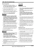
• Tighten the nuts in a cross pattern to the correct
torque value of 125 ft. lbs. (90 Nm). See Figure 2-2.
When the nuts stay tight for eight hours, the interval
for checking the torque can be extended to 200 hrs.
Figure 2-2 Tire Tightening Sequence
The truck is equipped with tires of a size and
hardness that provide the necessary traction and
still maintain a proper shape to minimize tipping.
To maintain stability and maximum reliability, you
must always replace tires with the type originally
supplied and torqued to specification, as listed
on the specification sheet on page 1-12.
https://www.forkliftpdfmanuals.com/

