background image

LANDI RENZO S.p.A.

‘SE 81 SIC’ LPG REGULATORS INSTALLATION AND ADJUSTMENT MANUAL

8 / 19

Notices

3. GENERAL NOTICES

To install the regulator, the following instructions
must be observed:
• install the regulator in the engine compartment
as close as possible to the point where the mixer
is to be installed, securing it integrally with the
bodywork using the screws provided;
• position the regulator away from air intake
components for the ventilation and heating of the
passenger compartment;
• position the regulator at a distance not inferior to
150 mm from the exhaust pipes or silencer. In
case the distance is inferior to the minimum value,
but not greater than 75 mm, it is necessary to
insert between the elements a metal sheet (or
equivalent material) with a minimum thickness of
1 mm.
• position the regulator in parallel with the direction
of travel and in an upright position so that it is
easily accessible to allow adjustment and
maintenance work;
• check that the regulator is placed in a lower
position than the highest point of the radiator in
order to prevent air bubbles forming in the water
circuit;
• take care not to position the regulator so that the
bleed plug is above the distributor or above the
ignition coil;
• carefully clean the tank and the LPG supply
pipes before they are finally connected to the
regulator to prevent any impurities getting inside
the regulator;
• check that with the engine running there is no
leakage from the water pipes (generally connected
to the passenger compartment heating circuit);
• check that the regulator heats up quickly by
means of the engine cooling circuit connection.

Every time the engine cooling circuit is emptied it
is necessary to restore the level of liquid, taking
care any air bubbles are eliminated as they could
prevent the regulator from heating.
The regulator gas outlet should be connected to
the mixer preventing the connecting pipe (which
must be as short as possible) from having any
bends or pockets.
The regulator is supplied with securing brackets to
position the regulator in the engine compartment.
These brackets will need to be adapted in relation
to the point of the engine compartment chosen for
securing.

Regulators setting

4. SETTING PROCEDURE FOR REGULATORS
TYPE ‘SE 81 SIC’

with exhaust gas analyser 

(Fig. 1)

4.1 CATALYSED CAR
The first step is to adjust peak speed:
• take the engine at about 3,500 r.p.m. until
reading on the Tester Programmer Mod. V05 that
the default value is recorded.

The second step is to adjust idling speed:
• with the engine running, turn the idle speed
setting screw (E) (clockwise it decreases,
anticlockwise it increases) until, on the Tester
Programmer Mod. V05, the number of steps of the
linear electromechanical actuator indicated in
menu ‘Display’ at the word MOT is equal (or as
close as possible) to the value indicated at the
word DEF.
• always check that the lambda scale LED’s
indicating carburation are flashing properly.
• Check by the gas analyser that the Lambda
value is about 1.000, CO and HC values are the
lowest possible (tending to zero) and CO

2

 value is

about 13-14% or the highest possible

.

For deeply details see ‘Instruction manual for
installation and adjustment Lambda Control
System A1 V05’ and ‘Tester Programmer Mod.
V05 instruction manual’ for the procedure of
recording the carburation.
Having regulated idling and peak speeds, carry
out a test on the road.

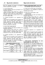
4.2 INJECTION CAR
The first step is to adjust peak speed:
• take the engine at about 3,500 r.p.m. and turn
the peak speed regulator located on the start
petrol solenoid valve, between the regulator and
the mixer, to take the values of CO, HC and CO

2

as shown in the table.

The second step is to adjust idling speed:
• with the engine running, turn the Idle speed
setting screw (E) (clockwise it decreases,
anticlockwise it increases) to take the values of
CO, HC and CO

2

 as shown in the table.

Having regulated idling and peak speeds, carry
out a test on the road.

Summary of Contents for SE 81 SIC

Page 1: ...LLACION Y REGULACION pag 16 RIDUTTORI SE 81 SIC GPL SE 81 SIC LPG REGULATORS REDUCTEUR SE 81 SIC GPL REDUCTORES SE 81 SIC GLP LPG CNG CONVERSION SYSTEMS FOR VEHICLES 190157440 1 LANDI RENZO S p A Via...

Page 2: ...LANDI RENZO S p A RID GPL SE81 SIC SE81 SIC LPG REG DET SE81 SIC GPL RED SE81 SIC GLP 2 19 Schemi Tecnici Technical Drawings Sch mas Techniques Esquemas T cnicos Fig 1 Fig 2...

Page 3: ...i sicurezza che interviene chiudendo le elettrovalvole del gas in caso di spegnimento anche accidentale del motore Funzionamento CARATTERISTICHE Tipo riduttore 2 stadi con dispositivo di avviamento el...

Page 4: ...cuito di riscaldamento dell abitacolo controllare che il riduttore si riscaldi rapidamente tramite il collegamento al circuito di raffreddamento del motore Ogni volta che viene vuotato il circuito di...

Page 5: ...il motore a circa 3 500 giri min e ruotare il registro del massimo posto sul tubo che collega riduttore e miscelatore in senso orario fino a quando non si noter una flessione del motore dovuta all im...

Page 6: ...ione accelerando lentamente Dopo i primi 500 1 000 Km preferibile controllare la sensibilit del riduttore Manutenzione 7 INTERVENTI DI MANUTENZIONE DELL IMPIANTO Per ottenere il meglio dal carburante...

Page 7: ...s solenoid valves if the engine is switched off or even stalled Operation SPECIFICATION Regulator type 2 stages with electronic starting device and idling at positive pressure Use automotive suitable...

Page 8: ...e mixer preventing the connecting pipe which must be as short as possible from having any bends or pockets The regulator is supplied with securing brackets to position the regulator in the engine comp...

Page 9: ...ing Sensitivity setting speed is obtained which is also to be checked after the road test Having regulated idling and peak speeds carry out a test on the road 6 SENSITIVITY SETTING PROCEDURE FOR REGUL...

Page 10: ...rer it is recommended every 15 000 km check replace the air filter change the spark plugs check the exhaust gas with an analyser check the efficiency of the electrical system check there is no oxide f...

Page 11: ...ique pour le d marrage dont fait partie un syst me de s curit qui intervient en fermant les lectrovannes du gaz si le moteur devait s teindre aussi accidentellement Fonctionnement CARACTERISTIQUES Typ...

Page 12: ...r ducteur se r chauffe rapidement travers le raccordement au circuit de refroidissement du moteur Apr s chaque vidange du circuit de refroidissement du moteur r tablissez le niveau R glage r ducteurs...

Page 13: ...lenti 1 25 1 50 3 500 g m 0 30 0 60 CO2 en Ralenti 12 14 3 500 g m 13 15 HC en ppm Ralenti 100 150 3 500 g m 20 60 R glage r ducteurs 5 R GLAGE DES REDUCTEURS SE 81 SIC sans analyseur gaz d chappement...

Page 14: ...vis de r glage de la sensibilit G 2 D marrer le moteur et r gler le ralenti travers la vis de r glage E jusqu atteindre la valeur maximale de CO2 Entretien 3 D visser lentement la vis de r glage de la...

Page 15: ...es avec ce carburant Toutefois pour ne pas compromettre le bon fonctionnement du dispositif d origine essence ainsi que celui de la pompe du carburant il est recommand de parcourir 2 3 Km au moins ess...

Page 16: ...l gas en caso de apagado incluso accidental del motor Funcionamiento CARACTER STICAS Tipo reductor 2 etapas con dispositivo de arranque electr nico y m nimo a presi n positiva Uso autotracci n para ve...

Page 17: ...conectados con el circuito de calentamiento del habit culo controlar que el reductor se caliente r pidamente mediante la conexi n con el circuito de refrigeraci n del motor Regulaci n reductores Cada...

Page 18: ...SIC sin analizador de gas de escape Fig 1 5 1 PARA AUTO INYECCI N CATALIZADOS Ver el punto 4 1 sin considerar el control con analizador gas d escape 5 2 PARA AUTO INYECCI N Y CON CARBURADOR La primera...

Page 19: ...ci n en el registro de sensibilidad G a fin de evitar manipulaciones 6 Controlar que no se verifiquen vac os de carburaci n acelerando lentamente Mantenimiento Al cabo de los primeros 500 1 000 Km es...

Reviews: