23
4
Design and Functions
4.2
Functional Description
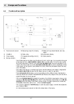
The F300K analyses the flickering of the flame in the UV or IR range. For preparation for signal
processing there is a
semiconductor sensor (1)
on a button strip. For each sensor signal,
the level is adjusted by means of two adjustable
amplifiers (2)
. These two amplifiers are lo-
cated on the main board, as are the
two microcontrollers (4)
. Due to the amplitude and the
course taken by the signal to be evaluated over time, both microcontrollers detect the exist-
ence of the flame.
The safety of the device is monitored by means of both software and hardware diagnostics.
The
ready contact (8)
indicates that the flame scanner is ready for operation.
The
mode selector (11)
allows you to choose between three different sets of parameters.
These parameters are stored in the EEPROM and influence the analysis of the current sensor
signal of the flame to be monitored.
There is a
FSB interface (9)
available for operation. The F300K is operated by means of an
external or
internal user interface (7)
or the PC with F300K-Remote-Software. An
LED dis-
play (10)
makes the status of the flame scanner visible. The flame intensity is provided as
non-failsafe information with a 4 (0) ... 20 mA
current loop (5).
The circuit is supplied with
24 VDC (3)
by an external power supply unit with safe separation
(e.g. FN20 or FN30).
An internal temperature sensor monitors the temperature in the device.
1
Semiconductor sensor
5
Measuring output for intensity
9
FSB bus for parameterisation and mes-
sages
2
Amplifiers
6
Flame relay
10
LED status display
3
Power supply
7
Integrated operating unit (UI)
11
Mode selector
4
Microcontrollers
8
Ready
Summary of Contents for F300K Series
Page 2: ......
Page 26: ...25 5 User Interface 5 2 Menu tree ...
Page 31: ...30 6 Commissioning Marking information on the device Example F300K F300K UI FB30 Warning e g ...
Page 121: ...120 14 Appendix 14 3 EU Declaration of Conformity ...
Page 122: ...121 14 Appendix ...
Page 125: ...124 14 Appendix ...


