40
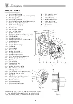
Fig-19
Fig-20
Fig-21
1 – Burner coupling plate
2 – Burner coupling plate lower locking screws
3 – Insulation gasket
4 – Burner locking screw
5 – Burner coupling plate upper locking screws
6 – Gas feed flange locking screws
7 – Mains connection plug
8 – Component holder plate
9 – Burner cover
10 – Electric motor capacitor
11 – Cover locking screw
12 – Ignition transformer
13 – Component holder plate locking screws
14 – Centrifugal fan
15 – Air adjustment valve
16 – Gas unit fixing screws in flame nozzle
17 – Lock reset button
18 – Control device
19 – Vacuometer coupling
20 – Fuel pump
21 – Flame nozzle
22 – Electric motor
23 – Ignition electrodes
24 – Air adjustment screw
25 – Air adjustment ring nut
26 – Pump pressure adjustment screw
27 – Pressure gauge attachment
28 – Nozzle
29 – Nozzle holder
30 – Pressurization ring
31 – UV photocell
32 – Ignition electrode cables
33 – Nozzle holder unit cover
retaining screw
34 – Nozzle holder pipe coupling union
35 – Fuel pump delivery union
36 – Sightglass
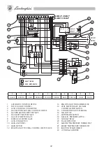
37 – Diesel oil/gas operating control
38 – Auxiliary relay
39 – Neutral terminal
40 – Air pressure switch
41 – Auxiliary terminal board
NOMENCLATURE
WARNING: IN THE EVENT OF DANGER, CUT THE POWER
BY TURNING OFF THE MAIN SWITCH AND CLOSE THE
FUEL FLOW BY MEANS OF THE SHUTOFF GATE VALVES.
42 – Gas pressure switch
43 – Gas electrovalve
44 – Oil electrovalve
45 – Remote locking light
46 – Boiler thermostat
47 – Ambient thermostat
48 – Main switch
49 – Fuse


