9
DIMENSIONS
��
�
�
�
�
�
�
��
�
�
�
�
�
��
�
������
������
Model
A
B
C
D
E
F
ØG
H
ØL
N
P
R
S
T
Twin 13
50
75 340 400
30
75 4 0 ÷ 50 0 80 600
450
0
5
Twin 13 L
675
80
PRESSURIZATION DIAGRAM
The curves shown in the diagram
were obtained by conducting the
combustion tests in accordance
with the flue specifications and
characteristics as set out in the
national and international regula-
tions in force.
Gas
Diesel oil
FIG. 3
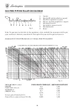
FUEL OIL FEED PIPES
Pipe development
Pipe development
Suction system
Gravity system
N.B. The diagrams are valid for fuel oil with a viscosity of max. .3°E at 0°C (3.78 cSt)
Fig. 4
A Suction pipe
B Fuel filter
C Suction pipe gate valve
D Flow stop electrovalve
E Return pipe gate valve
F Return pipe
G Foot valve


