35
Oil-powered burner
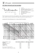
- Close the gas shutoff cock (B) (Fig. 5 Page 3).
- Bleed the gas from the pipe by loosening the pressure outlet connector (F) (Fig. 5)
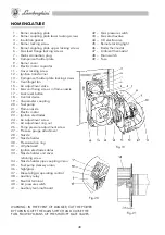
- Press the lock reset button (7).
- Turn on the power with the main switch.
After the pre-ignition time has elapsed, the burner starts and remains on until the temperature
set on the control device that intervenes first is reached (boiler thermostat, ambient thermostat,
etc.)
During normal operation the burner stops only when the control or drive devices intervene.
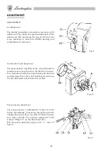
- Adjust the flame by appropriately acting on the air adjustment screw (4) and relevant ring nut
(5).
N.B. If the burner does not start, check that the pump has been primed. If not, operate manually by
loosening the pressure gauge attachment screw (7) and retighten it as soon as fuel oil starts to flow-
out. If several cycles are run during this operation, the burner must be reset each time by pressing the
lock reset button (7).
Gas-powered burner
- Open the gas shutoff cock (bleed the air from the pressure outlet connector) (F) (Fig. 5).
- Press the lock reset button (7).
- Close the main switch.
- The burner starts and after running the starting cycle the flame is formed and burns until a con-
trol device intervenes.
- As soon as the burner has started, adjust the gas flow rate on the regulator (see Fig. 3) and
the quantity of air by turning the screw (4) (Fig. 9).
N.B. It is essential during operation with gas to leave the fuel oil feed pipe gate valves open in order
to allow the fuel pump to operate.
- Read the gas flow rate on the counter (A) (Fig. 5) of the gas company.
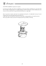
- For both oil- and gas-powered burners, combustion can be fine adjusted by longitudinally mo-
ving the pressurization ring (30) acting on the adjusting screw (A) (Fig. 0). Turning the screw
clockwise moves the ring forward and decreases the combustion air, turning it anticlockwise
moves the ring backward and increases the air. It is advisable to operate as instructed until
obtaining optimal combustion values and starting conditions.
As an approximate indication, the pressurization ring (30) must be positioned backward for opera-
tion with pressurized boilers with fuel flow rates close to maximum. Conversely, the pressurization
ring must be positioned forward for operation with little pressurized boilers or with reduced fuel flow
rates.
INSTALLATION

