


37
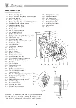
MAINTENANCE
WARNING: All the operations must be carried out after disconnecting the power by turning off the
main switch and pulling out the plug (7).
Remove the burner cover (9) to carry out the following checking and cleaning operations:
UV PHOTOCELL (3)
Remove and thoroughly clean the sensitive part using clean dry cloths. When refitting, make sure
that it fits securely into place.
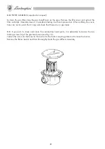
NOZZLE (8)
Remove the high-voltage cables (3) on the transformer side and the UV photocell (3). Unscrew
the cover retaining screws (33), unscrew the union (34) and the union (35) on the fuel pump, then
remove the nozzle holder unit (9) and electrodes. Unscrew the nozzle (8) from the holder taking
care not to alter the position of the ignition electrodes (3); should this occur, reposition everything
according to the dimensions indicated in Fig. 8.
N.B. To properly clean the nozzle, remove the filter and clean the grooves and the atomising hole
with petrol. Do not use tools that may damage the internal surfaces.
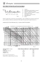
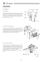
PRESSURE STABILISER (supplied on request)
To adjust the gas pressure, turn the screw indicated in Figure 6.
Tighten the screw to increase the pressure and loosen to decrease it.
The maximum burner capacity cannot be reached if the pressure upstream of the gas valve is not
between 5 and 3 mbar (50-30 mmHO).
N.B. The adjusting screw must never be at the end of travel, as the pressure stabilizer is unable to
function in this condition.
Fig-6