35
EN
cod. 3540S420 - 05/2010 (Rev. 00)
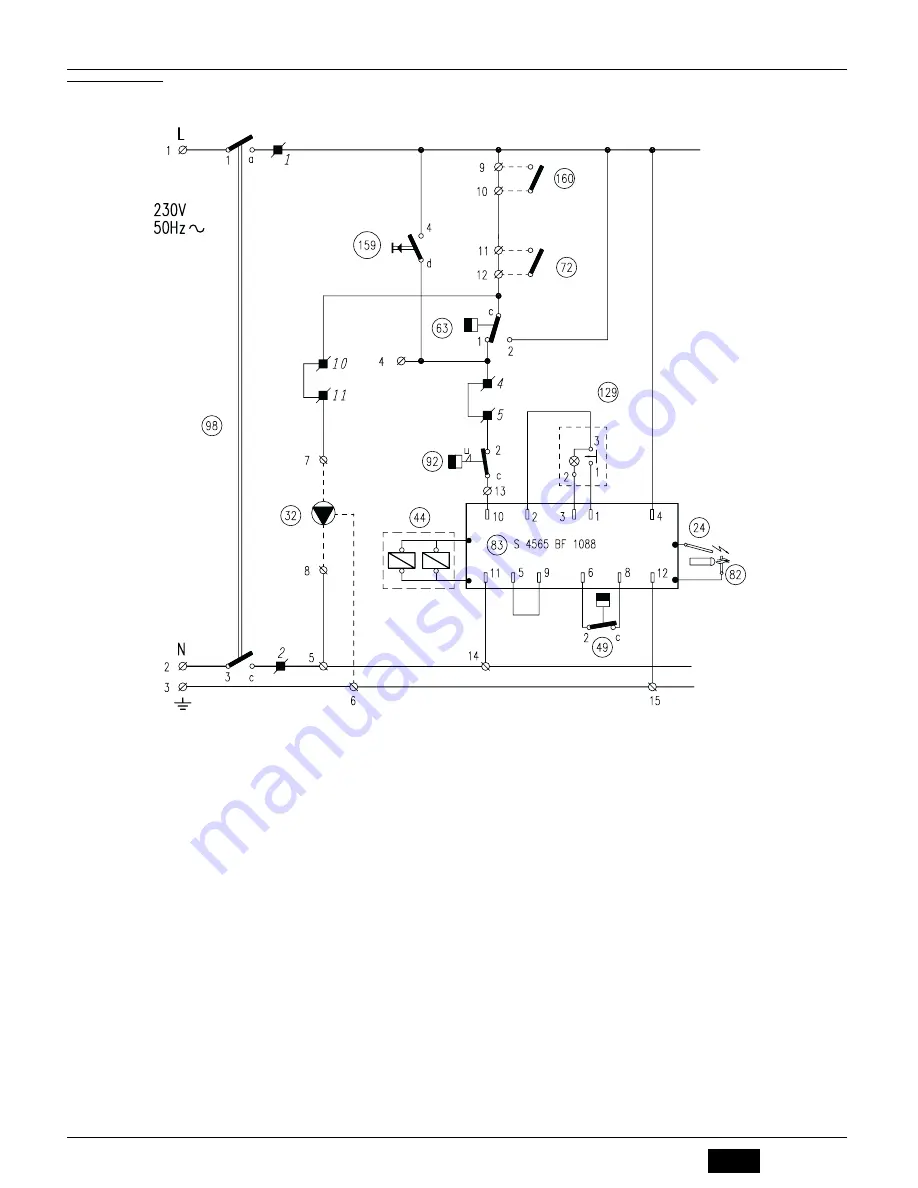
5.5 Wiring diagrams
Main wiring diagram
fig. 14 - Main wiring diagram
24
Ignition electrode
32
Heating circulating pump
44
Gas valve
49
Safety thermostat
63
Boiler control thermostat
72
Room thermostat (not supplied)
82
Detection electrode
83
Electronic controller
92
Fume thermostat
98
Switch
129
Reset button with indicator lamp
159
Test button
160
Auxiliary contact
A
Connections in broken lines carried out by the installer
Summary of Contents for GASTER N 56 AW
Page 10: ......
Page 19: ......
Page 28: ......
Page 49: ...49 RU cod 3540S420 05 2010 Rev 00 1 2 3 4 5 6 7 8 4 4 1 fig 10 3 3 4 mm 5 4 8 10 40 C...
Page 51: ...51 RU cod 3540S420 05 2010 Rev 00 5 5 14 24 32 44 49 63 72 82 83 92 98 129 159 160 A...
Page 52: ...52 RU cod 3540S420 05 2010 Rev 00 15 24 32 44 49 63 72 82 83 92 98 129 159 160 A...
Page 63: ......


