- 37
-
ENGLISH
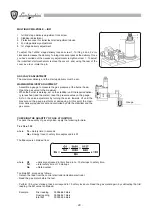
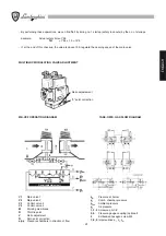
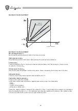
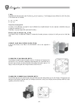
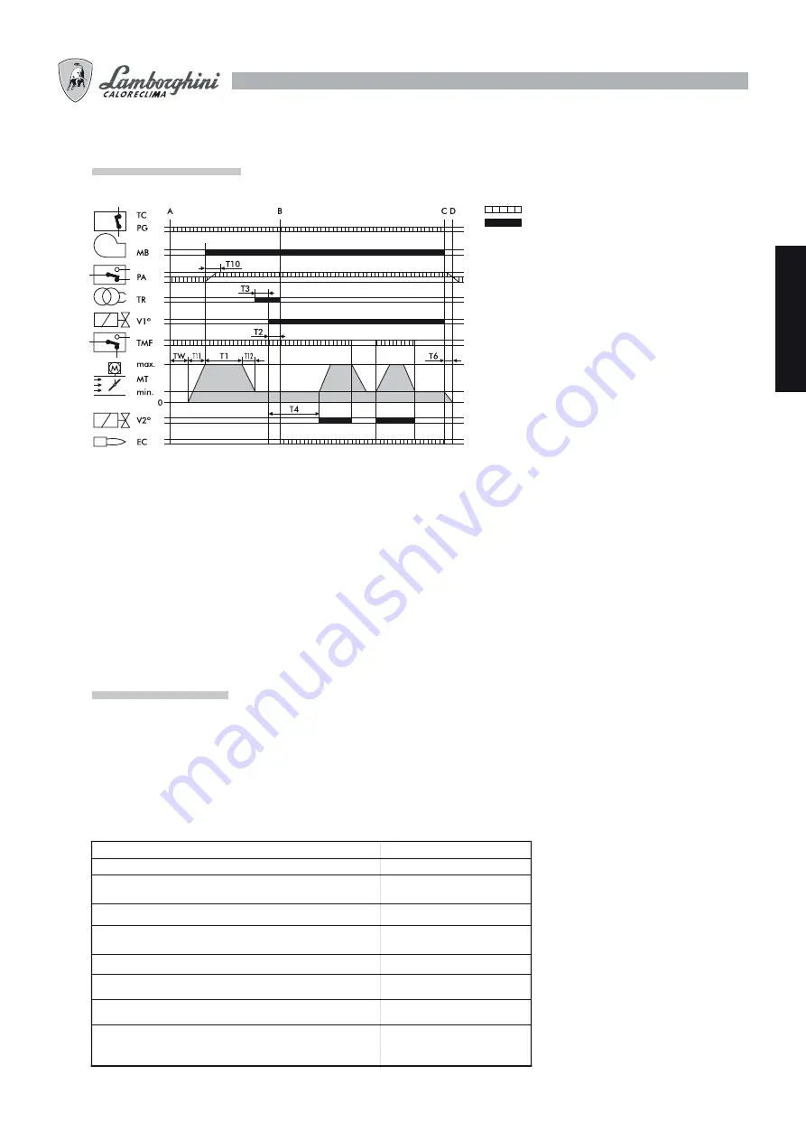
OPERATING CYCLE
LME EQUIPMENT
The release pushbutton on the equipment is the main component for accessing all the diagnostic functions (activation and
deactivation) as well as for releasing the control and checking device. The release pushbutton has a multicoloured led
which indicates the state of the control and checking device during operation and when the diagnostic function is in use.
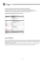
EQUIPMENT STATE INDICATORS
Description
Condition Colour
sequence
Standby, other intermediate states
No light
Ignition stage
Yellow, flashing
Correct operation
Green
Incorrect operation, current level of
flame detector below permitted minimum
Green, flashing
Drop in voltage
Alternating yellow red
Burner lock out
Red
Fault (see table)
Red, flashing
Stray light before burner ignition
Alternating green red
Rapid flashing for diagnostics
Red, rapid flashing
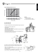
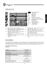
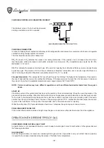
T11
Air shutter opening time, from 0 to max.
TW
Begins with the closure of the thermostatic line or
the PG. The PA must be in the rest position. This is
the waiting and self-test time lasting.
T10
Begins when the motor starts up and with the pre-
purge phase; it lasts for 3 seconds,
within which the PA air pressure switch must give
the go-ahead.
T1
Pre-purge time, which lasts for at least 30 seconds,
ending when the transformer
starts
up.
T3
Pre-ignition phase, it ends when the gas valve
opens. It lasts for 3 seconds.
T2
Safety time, within which the flame signal must
reach the EC electrode. It lasts for 3 seconds.
T4
Interval between the opening of the V1 gas valve
and the opening of the second
stage V2. It lasts for 8 seconds.
T6
Air shutter closing time and program zero-setting
time.
T12 Time in which the air shutter shifts to the start-up
position.
Necessary input signals
Output
signals
A
Begin start up
B Flame
present
B-C Operation
C Control
stop
TMF
High/low flame thermostat
C-D
Air shutter c post-purge
TC-PG
Thermostats/Gas pressure switch line
MB Burner
motor
PA
Air pressure switch
TR Ignition
transformer
V1°-V2° 1st/2nd stage gas valve
EC Control
electrode
MT
Air servo control
Summary of Contents for EM 40/2-E
Page 2: ......
Page 25: ...25 ITALIANO...
Page 47: ...47 ENGLISH...
Page 69: ...69 FRAN AIS...
Page 91: ...91 DEUTSCH...
Page 113: ...113 ESPA OL...
Page 115: ...115 a b c d CO2 CO2 CO2...
Page 116: ...116 119 133...
Page 120: ...120 2 n 4 3 4 5 1 A B C D...
Page 121: ...121 2...
Page 126: ...126 3 sec 3 sec LME 10...
Page 127: ...127 B 1 2 3 B H EM 35 E H H EM 40 2 E EM 40 M E H fi 1 max E E 1 E 2 E VE 2 2 14 10 13 SQN 71...
Page 132: ...132 3 A CO2 CO2 CO2 8 5 10 11 12 B P CO CO CO 0 1 160 C 220 C TPR TS B P...
Page 134: ...134 1 A B A B 2 A B C A B C 3 A A...
Page 135: ......

