- 28
-
•
The room where the burner is housed should be kept clean at all times, and there should be no volatile substances in the
vicinity, substances which could be sucked into the fan and could block up the internal ducts of the burner or combustion
head. Dust can be extremely harmful, particularly when it gets onto the fan blades as this can reduce ventilation and
lead to pollution during combustion. Dust can also build up on the rear of the flame stability disk inside the combustion
head, leading to a poor air-fuel mixture.
•
The burner must be fed with the type of fuel for which it was designed, as indicated on the data plate and in the technical
characteristics given in this manual. The fuel feed line must be sealed and must be of the rigid variety, with an interposed
metal expansion coupling with either a flange joint or a threaded joint. Furthermore, the feed line must be equipped with
all the adjustment and safety devices required by the local regulations in force. Particularly ensure that no foreign bodies
get into the feed line during installation.
•
Ensure that the electrical power supply used conforms to the technical characteristics indicated on the data plate and in
this manual. The burner must be connected to an effective system earthed in accordance with the current regulations.
Should there be any doubts, the verification should be made by qualified persons.
•
Never exchange neutral and phase wires.
•
The burner can be connected up to the mains supply using a plug connection only if the latter is of the kind that does
not allow neutral and phase wires to be reversed. Install a main switch for the heating system on the control panel, as
required by current regulations.
•
The entire electrical system, and in particular cable cross-sections, should conform to the maximum absorbed capacity
indicated on the appliance data plate and in this manual.
•
Should the burner’s mains cable be found faulty, it must only be replaced by qualified persons.
•
Do not touch the burner with parts of the body which are wet or when in bare feet.
•
Do not pull (stretch) the mains cables and keep them well away from heat sources.
•
The length of the cables used must enable the burner to be opened, as well as the boiler door.
•
The electrical connections must be made exclusively by qualified experts and the relative regulations in force must be
scrupulously applied.
•
After removing the packaging materials, check the content integrity and make sure that no damages have occured during
transportation. In case of doubt, do not use the burner and contact the supplier. The packaging material (wooden cages,
cartons, plastic bags, foam, clips, etc...) are potential sources of pollution and danger, if left lying around; they should be
collected up and disposed of in the correct way (in a suitable place).
DESCRIPTION
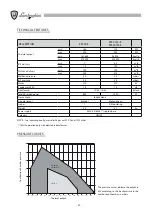
These are forced-draught burners with gas/air mix at the combustion head: one and two-stage ignition versions, as well as
modulating versions are available. The burners are completely automatic and equipped with controls assuring maximum
safety. They can be combined with any type of chamber whether in negative or positive pressure, within the foreseen
working range.
The burners are supplied without a gas train and must therefore be completed with the train most suitable for the system in
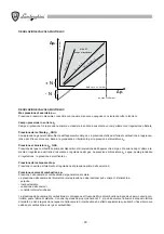
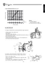
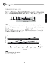
which the burner is to be fitted. The gas train is therefore chosen by consulting the diagram (pages 31-45); this illustrates
pressure loss as a function of mains gas pressure, required gas delivery at the appliance and the back-pressure in the
combustion chamber.
All the components can be easily inspected without having to disconnect from the main gas supply. The burners are equip-
ped with a cover which means they are particularly compact, soundproof and safeguarded.
Summary of Contents for EM 40/2-E
Page 2: ......
Page 25: ...25 ITALIANO...
Page 47: ...47 ENGLISH...
Page 69: ...69 FRAN AIS...
Page 91: ...91 DEUTSCH...
Page 113: ...113 ESPA OL...
Page 115: ...115 a b c d CO2 CO2 CO2...
Page 116: ...116 119 133...
Page 120: ...120 2 n 4 3 4 5 1 A B C D...
Page 121: ...121 2...
Page 126: ...126 3 sec 3 sec LME 10...
Page 127: ...127 B 1 2 3 B H EM 35 E H H EM 40 2 E EM 40 M E H fi 1 max E E 1 E 2 E VE 2 2 14 10 13 SQN 71...
Page 132: ...132 3 A CO2 CO2 CO2 8 5 10 11 12 B P CO CO CO 0 1 160 C 220 C TPR TS B P...
Page 134: ...134 1 A B A B 2 A B C A B C 3 A A...
Page 135: ......

