Lake Shore Model 647 Magnet Power Supply User’s Manual
Table of Contents
iv
LIST OF ILLUSTRATIONS
Figure No.
Title
Page
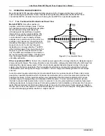
1-1 Four-Quadrant Power ..................................................................................................................... 1-4
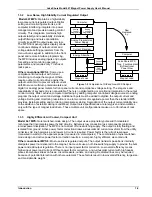
1-2 Comparison of Old and New MPS Designs.................................................................................... 1-5
2-2 RI, FLT, ON, and OVP Connections ............................................................................................... 2-4
2-3 Analog Monitoring, Programming, & Remote Sense Connections................................................. 2-5
2-4 Remote Sensing Connections ........................................................................................................ 2-6
2-5 Typical Multiple MPS Connections for Two MPS Units .................................................................. 2-8
3-1 Front Panel Numeric Entry Keys..................................................................................................... 3-1
4-1 Typical National Instruments GPIB Configuration from IBCONF.EXE ........................................... 4-7
4-2 Serial Interface Adapters ................................................................................................................ 4-8
5-1 Rear Panel Connectors................................................................................................................... 5-6
5-2 Serial Interface Connector .............................................................................................................. 5-6
5-3 IEEE-488 Connector ....................................................................................................................... 5-7
5-4 Model 2001 RJ-11 Cable Assembly Wiring ....................................................................................
5-7
5-5 Model 2002 RJ-11 to DB-9 Adapter Wiring .................................................................................... 5-7
5-6 Model 2003 RJ-11 to DB-25 Adapter Wiring ..................................................................................
5-7
LIST OF TABLES
Table No.
Title
Page
1-1 Model 647 DC Output Specifications.............................................................................................. 1-3
2-1 MPS Line Voltage Limits ................................................................................................................. 2-2
2-2 Load Wire Lengths and Current Capacity....................................................................................... 2-3
2-3 RI, FLT, ON, and OVP Connections ............................................................................................... 2-4
2-4 Analog Monitoring, Programming, and Remote Sense Connections ............................................. 2-5
2-5 Connections for a Two-MPS Autoparallel Configuration ................................................................ 2-8
4-1 Sample Basic IEEE-488 Interface Program.................................................................................... 4-6
4-2 Serial Interface Specifications......................................................................................................... 4-9
4-3 Sample Basic Serial Interface Program.......................................................................................... 4-10
5-1 Rear Panel Connector Definitions................................................................................................... 5-6
5-2 Serial Interface Connector Definition .............................................................................................. 5-6
5-3 IEEE-488 Interface Connector Definition........................................................................................ 5-7
A-1 Units for Magnetic Properties.......................................................................................................... A-1
B-1 MPS Mainframe Control Bus Remote Command Summary .......................................................... B-5
B-2 Additional MPS Mainframe Control Bus Remote Commands ........................................................ B-6


