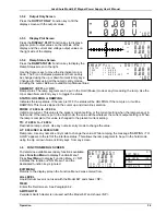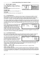
Lake Shore Model 647 Magnet Power Supply User’s Manual
Operation
3-4
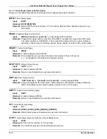
3.7 FUNCTION MENU 3 SCREEN
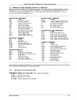
Press
Function Menu
to display Function Menu 1.
Press
Next Menu
twice to display Function Menu 3.
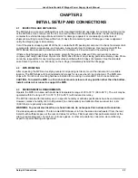
EXIT MENU
Returns to the display screen the Function Menu 3
was entered from.
CURRENT ZERO
Enters the Current Zero screen. See Paragraph 3.7.1.
I STEP LIMIT
Enters the Current Step Limit screen. See Paragraph 3.7.2.
3.7.1 Current Zero Screen
Remotely program MPS current and voltage by external voltages or potentiometers in addition to internal
digital programming. Enable external analog programming via the rear panel MODE switches. When the
mode switch is in the INT I or V position, external current or voltage programming mode is disabled. When it
is in the EXT I or V position, external programming voltage sums with internal programming voltage.
There may be configurations, like multiple auto-parallel MPS units, that introduce an output current offset from
zero. This small offset current may translate into a large energy stored in the magnet load. The output current
zero feature allows users to zero this output current offset from the MPS front panel. The current zero feature
is enabled when either internal or external programming is used. The current zero value stores in non-volatile
MPS memory.
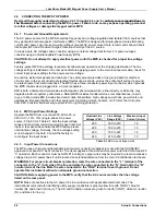
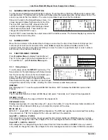
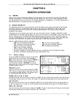
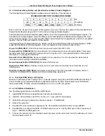
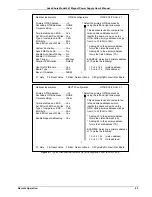
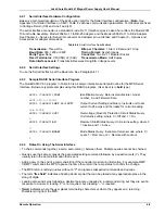
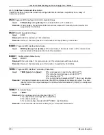
Access output current zero from the MPS front panel.
Enter a current setting of zero and allow the output
current to settle to the offset value. Press the
CURRENT ZERO Function key on Function Menu 3 to
display the Current Zero screen with the output
values. The Up or down Numeric Entry keys toggle
the status. If the status is ON, it must be toggled to
OFF to clear the old value before a new value is accepted. When the status is toggled ON, the output current
stores as the current zero and displays as the I ZERO value.
3.7.2 Current Step Limit Screen
When a superconducting magnet quench occurs, the magnet becomes resistive. The output current forces
MPS output to the voltage setting (constant voltage mode) and output current drops rapidly. To avoid
excessive cryogen boil off, the output current setting should be changed to 0 as quickly as possible.
The output current step limit feature allows users to
enter a current step limit which, if exceeded,
automatically resets the output settings to 0A and 1V.
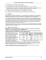
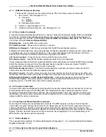
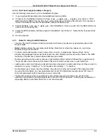
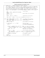
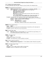
Press the I STEP LIMIT Function Key on Function
Menu 3 to display the Current Step Limit screen.
Use the Cursor keys to move the line indicator up and
down. The
¥
icon indicates parameters that can only be changed using the up or down Numeric Entry keys.
Change all others using all the numeric entry modes, including the cursor. (See Section 3 for keypad
operations.) Below are valid Output Current Step Limit entries:
STATUS:
<OFF> or <ON>
Output Current Step Limit Status. Use the Up or down Numeric Entry keys to toggle the status.
I STEP + 0.00 A to + 999.99 A
Output Current Step Limit. Use any numeric entry mode to change the value. If the MPS detects a change in
output current that exceeds the step limit, it enters Step Limit Mode and forces output settings to 0 amps and
1 volt. On the next update cycle, it closes the FLT contacts to indicate the fault and the internal audio indicator
beeps about once per second. See Chapter 5 for error messages and action to take if the Current Step Limit
is exceeded.
3/ 3
EX IT M E NU
CU R R E N T ZE R O
I ST EP L IM IT
¤
IM A X S E T :+ 7 2 .0 0 A
V M A X S E T :+ 3 2 .0 0 V
S E T T IN G S :
+ 0 .0 0 A
1.0 0 V
: <O F F >
: + 0 .0 0
: IN T E R N A L
- 0 .0 0 A
+ 0 .0 0 V
L O C
C U R R E N T Z E R O :
¤ S T A T U S
I Z E R O
I M O D E
O U T P U T :
¥
*
: <O F F >
: + 10 .0 0 A
- 0 .0 0 A
+ 0 .0 0 V
L O C
C U R R E N T S T E P L IM IT :
¤ S T A T U S
I S S T E P
O U T P U T :
¥
*

