Lake Shore Model 647 Magnet Power Supply User’s Manual
Setup & Connections
2-3
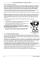
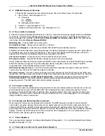
Use this procedure to connect input power to the MPS:
1.
Loosen the two connector cover screws and open the cover.
2.
Slip the strain relief over the power cable with the flanged end at the end to be terminated.
3.
Attach the wires to the connector in accordance with prevailing color codes: green or green/yellow to the
“GND” terminal, white or blue to the “N” terminal, and black or brown to the “L” terminal.
4.
Position the strain relief, close the cover, and then tighten the cover screws.
5.
Connect the other end of the power cord to an appropriate AC power source.
6.
Plug the power cord into the detachable power connector plug on the MPS rear panel.
2.5 POWER
UP
Read and follow instructions in Paragraphs 2.1 - 2.4.3 and safety recommendations in the Forward before
applying power to the MPS. Do not connect the MPS to the magnet at this point. Short the output terminals
together with a #4 gauge or larger cable. This protects the magnet against incorrect configurations.
Turn on the MPS. It requires approximately 2 seconds for initialization. Initially, all front panel annunciators
come on and the alarm sounds for a short time. Within 1 second, the Fault and Persistent Switch Heater On
annunciators and the alarm turn off. If the MPS detects a high or low AC line fault, it blinks the front panel
Fault annunciator and turns off the input circuit breaker. If this occurs, verify that the AC source matches the
line voltage listed on the MPS rear panel. The MPS front panel AC On LED lights any time the MPS is
connected to the AC line and the MPS power switch is ON.
Initially, the entire display clears and the alarm sounds for a short time. The MPS initializes itself and displays
the model identification. The Normal Display screen appears with a blinking asterisk indicating each update
when the unit is in normal operation.
2.5.1 Magnet Cable Connections
WARNING: Turn off the AC power before changing any rear panel connections and verify that all
connections are securely tightened before reapplying power.
CAUTION: Initially, setup the MPS without connecting it to the magnet. This lessens the chance for
inadvertent damage to the load while the user learns MPS operation.
Make MPS load connections at the
+OUT and –OUT terminals on the rear
panel. These plated copper bus bars
accommodate 1/4 inch mounting
hardware. Use load wires heavy
enough to limit the voltage drop to less
than 0.5 volts per lead. This ensures
proper regulation and prevents
overheating while carrying the output
current. Use remote sensing to
compensate for any voltage drop in the
load leads and obtain a more accurate voltage reading. Stranded AWG #4 wire is capable of carrying in
excess of 125 amperes. Keep conductor temperature under 85 °C for a 35 °C ambient. Table 2-2 lists the
ampere capacity and total +OUT and –OUT lead lengths for load connections.
If connecting multiple loads to the unit, use separate pairs of wires to connect each load to the output
terminals. Cut each pair of connecting wires as short as possible.
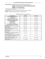
Area
Capacity
Resistivity
Total Lead Length (feet)
AWG (mm
2
) Amperes
Ω
/1000 feet
75 A
100 A
125 A
0
2
4
6
8
53.5
33.6
21.2
13.3
8.4
245
180
135
100
75
0.09827
0.1563
0.2485
0.3951
0.6282
135
85
53
33
21
101
64
40
25
—
81
51
32
—
—
Table 2-2
Load Wire Lengths and Current Capacity

