


Lake Shore Model 647 Magnet Power Supply User’s Manual
Introduction
1-2
1.2 SPECIFICATIONS
Below are performance specifications for current with a 1 Henry load and voltage with a resistive load.
DC Output:
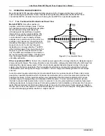
True, Four-Quadrant, Bidirectional Power Flow output. Autoranging current and voltage operate
as a source or a sink in either polarity in current or voltage mode. Program current and voltage via the front
panel, remote interfaces, or analog input. See Table 1-1 for DC Output Specifications.
Current: 0 to ±72 A
Voltage: 0 to ±32 V
Maximum Power: 2 kVA continuous
Remote Sensing
: Corrects for load lead drop of up to 0.5 V per lead. Operation with more drop per load lead
is possible with a degradation of the load effect specification.
Output Terminals
: The two rear panel output bus bars are isolated from the chassis (earth) ground.
Multiple Unit Operation
: Connect up to four units in an auto-parallel configuration for increased output current.
Protection
: Front panel annunciators, an audio indicator, and a contact closure indicate faults.
Remote Inhibit (RI)
: An active RI forces output settings to 0 A and 1 V until the RI is no longer active. To
continue normal operation, enter new output settings.
Output Inhibit (OI)
: Press the front panel OI key to force output settings to 0 A and 1 V. To continue normal
operation, enter new output settings.
Output Current Step Limit
: The output current settings are forced to 0 A and 1 V if a preset current step limit
is exceeded. A key entry is required to continue operation.
Utility Low Line or Loss:
Maintains operation until load is discharged or utility is restored.
Utility High Line
: Turns off input and maintains operation until load is discharged.
Overvoltage
: Crowbars output when output terminal voltage, induced by the load exceeds ±40 VDC.
Overtemperature
: Crowbars output and turns off input when internal heat sink temperature exceeds 95 °C.
AC Input
: Factory set for operation from 200, 208, 220, or 240 VAC (–10%, +5%), 50 to 60 Hz, single phase.
Input Protection
: A front panel 20 A two-pole circuit breaker protects the AC input. The MPS turns off the
breaker in the event of a fault.
Remote Interfaces
: RS-232C is standard; IEEE-488 is optional. All front panel functions can be controlled
over the interfaces. In addition, interfaces output displayed quantities.
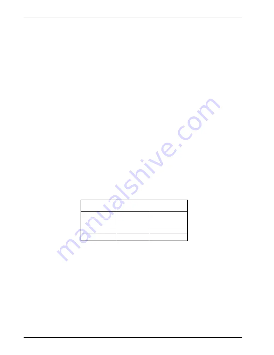
Input Current:
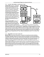
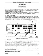
Front Panel
: Contains a menu driven keyboard and graphic display for entry and display of results. Operating
parameters to set and monitor from the front panel (and remote interface) include:
• Output current and voltage setting
• Output current and voltage measurement
• Status reporting
• Output ramp programming
• "Soft" current and voltage setting limits
• Field Monitoring (with optional Model 6476 Card)
• Output Current Zeroing
• Output Current Step Limiting
Magnet inductance and maximum charging voltage (di/dt = V/L) limit the output ramp programming charging
current. Program output for a constant 0.01 to 99.99 amperes per second as long as di
max
/dt is not exceeded.
Energize or de-energize the magnet at a pre-set voltage limit or ramp rate. Pause the ramp at any time during
the ramp. During a pause, the MPS maintains output values until the ramp continues.
Nominal Line
Voltage (VAC)
Line Voltage
Range (VAC)
Maximum Input
Current (A rms)
200
180 to 210
16
208
188 to 218
15
220
198 to 231
14
240
216 to 250
13