background image


20 

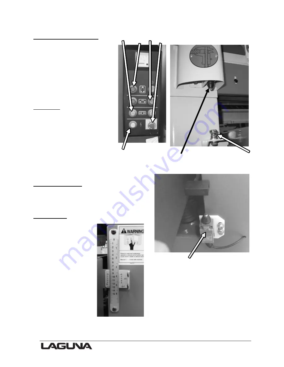
Electronic control panel  

The control panel is set on the 
front of the machine. It has a 
number of switches.  

1.

 Bed up/down buttons. 

2.

 Sanding belt start/stop 

buttons. 

3. 

Conveyor start/stop buttons. 

4.

 Emergency stop switch. 

5.

 Power indicator light. 


Quick set  

The sander has a device on the 
side that is used to set the 
height of the bed without 
measuring the job. Simply put 
the job on the height setting 
button, press and hold the 
arrow up button. The table will 
move up until the job hits the 
micro switch. The distance between the 
sanding head and the job is now set.  
 

Down limit switch  

The sander is fitted with a limit switch located 
at the back of the machine. This limit switch 
limits the down travel of the bed. 
 

Vertical rule  

There is a vertical 
quick reference rule 
that can be used to 
check the distance 
between the sanding 
head and the bed of 
the machine. 


1

         2     

3


 4 


5   

Control panel 

Quick set 


Micro switch 

  Height setting button


Down limit switch 


Summary of Contents for MSANWB25X60-1K-7.5-0197

Page 1: ...5 0197 Part No MSANWB37X60 1K 15 0197 2018 Laguna Tools Inc All rights reserved LAGUNA TOOLS 2072 Alton Parkway Irvine California 92606 Ph 800 234 1976 www lagunatools com Widebelt Sander Manual Mode...

Page 2: ......

Page 3: ...Where to locate your Widebelt Sander 13 Unpacking your Widebelt Sander 14 Assembly and Setup 15 Adjusting the Widebelt Sander 19 Running the Sander 24 Maintenance and Troubleshooting 27 Electrical Dra...

Page 4: ...llowing carefully before operating the machine 1 Keep the working area clean and be sure adequate lighting is available 2 Do not wear loose clothing gloves bracelets necklaces or ornaments Wear face e...

Page 5: ...empted by others Laguna Tools Inc is not responsible for additional tools or modifications sold or performed other than from by Laguna Tools Inc on any Laguna Tools Inc machine Warranty maybe voided u...

Page 6: ...tary precautions The factors affecting the true level of exposure to operators are clearly the amount of time exposed and the characteristics of the working environment such as other sources of dust a...

Page 7: ...7 Specification Sheet for Widebelt Sander...

Page 8: ...as soon as is practical Note It is probable that you will find sawdust within your machine This is because the machine has been tested prior to shipment from the factory and or Laguna Tools Laguna Too...

Page 9: ...ng rollers 3 Manual bed vertical adjusting handle This handle is used to manually adjust the bed vertically 4 Bed The bed of the sander has a rubber drive belt that transports the job through the mach...

Page 10: ...8 Air supply A clean dry air supply with a minimum pressure of 6 bar must be connected to the sander If the pressure drops below 5 bar the machine will stop functioning 9 Electrical control box The el...

Page 11: ...elt oscillation As the belt moves in and out of the sensor a piston moves a cam that is attached to the top sanding roller This action changes the angle of the top roller and forces the belt to move a...

Page 12: ...centrally on the top roller 20 Sanding belt oscillation piston The sanding belt oscillation piston moves a cam that is attached to the top sanding roller This action changes the angle of the top rolle...

Page 13: ...ng belts Before you remove your machine from the packaging select the area where you will use your machine There are no hard and fast rules for its location but below are a few guidelines 1 There shou...

Page 14: ...RY 2 Dismantle the box 3 Remove any bolts that secure the machine to the base if fitted Note You may find that the machine is bolted to the base through the frame To access the bolts both side panels...

Page 15: ...the sander for Connect to your dust collector with 5 inch dust hose You will need a dust collection system with a minimum airflow of 65 feet per second and of 3500 cubic feet minute The sander produc...

Page 16: ...um is required for the machine It is strongly recommended that 7 bar be supplied to the machine and that the regulator then be set to 5 5 bar This will ensure that the machine always has the minimum r...

Page 17: ...lease and needs only to be rotated approximately 90 degrees to release 3 Remove the spacer This will allow access for the sanding belt 4 Slide the sanding belt onto the top and bottom rollers Note Ens...

Page 18: ...when a belt will break or wear out Note The sanding belt must be positioned centrally on the rollers It must also be between the forks of the belt sensor Choosing sandpaper The grit type that you cho...

Page 19: ...ing belt should start run and stop smoothly 5 Let the sander run for a few minutes and listen for unusual noises or vibration If any unusual noises or excessive vibration is detected correct the probl...

Page 20: ...he job on the height setting button press and hold the arrow up button The table will move up until the job hits the micro switch The distance between the sanding head and the job is now set Down limi...

Page 21: ...he machine 2 Remove the conveyor drive cover 3 Remove the split link 4 Move the chain to the other set of gears 5 Refit the split link and the conveyor drive cover On the MSANWB37X60 1K 15 0197 there...

Page 22: ...ide of the bolt To ensure there is no leakage during shipping the hole is sealed with a small plastic pin Before the machine is run this pin must be removed This will allow the oil to expand without c...

Page 23: ...e sensitivity of the non contact air sensor can be adjusted by rotating the control knob 5 This has been factory set and should not need adjustment The speed of the belt oscillation can be increased o...

Page 24: ...Press the sanding belt start button The sanding belt will start to rotate 7 Open the left hand door and check that the sanding belt oscillations are central on the rollers You will probably find that...

Page 25: ...machine prior to testing it 1 Plug in the electrical supply 2 Switch on the sanding machine momentarily Check that the sanding belt is running true and balanced on the rollers 3 If the belt is not run...

Page 26: ...ve belt running press the emergency stop button The machine must stop 5 With the sanding belt running press the sanding belt stop button The sanding belt must stop 6 With the drive belt running press...

Page 27: ...of operation replace the oil in the conveyor drive gearbox Repeat the oil change every 2 500 hours Recommended oil is 90 wt gear oil Drive belt The drive belts should last for a long time depending on...

Page 28: ...se access to the bearings Grease nipple Grease nipple Grease nipple Grease nipple with cover removed Grease nipple Sanding belt non contact air sensor There are holes in the sensor for the air to esca...

Page 29: ...lace the felt pad remove the old felt pad Using a small amount of contact adhesive attach the new felt pad to the platen 5 Replace the platen into the sanding machine Note Ensure that the graphite pad...

Page 30: ...on such variables as the depth of cut hardness of the wood and other factors Experimentation will be required to achieve the correct setting It is suggested that setting the pressure rollers to 0 020...

Page 31: ...yor belt turn the adjusting bolts counter clockwise Note Adjust both adjusting bolts exactly the same amount or the tracking will be affected Motor drive belt adjustment Lock nut Break Sanding head dr...

Page 32: ...tor 2 Check the thickness of the disc pads The pad is constructed from a metal backing plate and breaking material The breaking material must be a minimum of 1 8 thick If either of the pads is thinner...

Page 33: ...ection blockage Sanding belt slows down during a cut Feeding the wood too fast Slow down the feed rate Dull sanding belt Replace the sanding belt Low voltage Check the incoming voltage to the machine...

Page 34: ...ted or scratched Dirty pressure rollers Clean pressure rollers Job has glazed marks or scratches snaking along the job Glazed sanding belt Clean or replace sanding belt Poor sanding results Worn sandi...

Page 35: ...on for the jamming Motor faulty Replace the motor Motor break locked on Release break Motor overheats The motor is designed to run hot but should it overheat it has an internal thermal overload protec...

Page 36: ...rn Replace conveyor belt Pressure roller not exerting correct pressure on job Adjust pressure rollers Conveyor belt not running in center Conveyor belt not tracked Adjust conveyor belt Conveyor belt w...

Page 37: ...slips on rollers Tension cylinder not exerting sufficient pressure Check for air leaks Low air pressure Sanding belt will not start No tension on the sanding belt No air pressure Limit switch engaged...

Page 38: ...38 Electrical Drawing...

Page 39: ...39 Electrical Drawing...

Page 40: ...40 Exploded View Drawings...

Page 41: ...E HOLDER 002 LIMIT SWITCH TUBE 003 TOOL BOX 004 FELT 005 GRAPHITE 006 KEY 007 1 SANDING BELT 100 007 2 SANDING BELT 180 008 PHILLIP S SCREWDRIVER 009 FLAT SCREW DRIVER 010 WRENCH 8 X 10 011 WRENCH 12...

Page 42: ...42...

Page 43: ...G 119 BELT 121 BRAKE BRACKET 122 PLAIN WASHER 3 8 123 SCREW 3 8 X 3 4 124 FLAT HEAD NUT 125 HEX SOCKET HEAD SCREW 1 4 X3 4 1000 ITEM NO DESCRIPTION 126 LIMIT SWITCH 127 LIMIT SWITCH PLATE 128 SCREW 1...

Page 44: ...44...

Page 45: ...BASE 323 SCREW 1 4 X 1 324 SPRING WASHER 1 4 325 MOTOR BASE ADJUSTMENT ROD 326 PLAIN WASHER 1 2 327 NUT 1 2 328 SPRING WASHER 1 2 331 MOTOR 332 NUT 1 4 333 SCREW 1 2 X 4 1 2 LONG 308 BEARING CAP 309 H...

Page 46: ...46...

Page 47: ...119 KEY 123 MOTOR 124 SPRING WASHER M10 127 SCREW M10 131 INFEED ROLLER BRACKET 132 HEX SOCKET HEAD SCREW 3 8 133 INFEED ROLLER BRACKET 135 CONVEYOR BELT POSITIONING WHEEL 136 HEX SOCKET HEAD SCREW 5...

Page 48: ...48...

Page 49: ...102 PISTON BRACKET 103 SPRING 104 PIN 10M M X 35M M 105 HEADLESS SCREW 1 4 106 SCREW 5 16 107 NUT 5 16 108 SCREW 5 16 109 SPRING WASHER 5 16 201 PISTON ROLLER SHAFT 202 PISTON ROLLER 203 BEARING 6001...

Page 50: ...50...

Page 51: ...ER 203 HEX SOCKET HEAD SCREW M6 X 6MM 204 BEARING UCC 205 5000 ITEM NO DESCRIPTION 309 FASTENING TUBE 310 HEADLESS SCREW 1 4 X 3 8 311 KEY 1 4 X 25MM 312 SPRING 313 HOUSING OF FIXING SHAFT 314 FIXING...

Page 52: ...52...

Page 53: ...RACKET 204 BEARING UCC205 205 HEADLESS SCREW M6 X 6MM 206 HEX SOCKET HEAD SCREW 3 8 X 3 4 207 SPRING WASHER 3 8 208 FILTER 212 HEX SOCKET HEAD SCREW 3 8 X 3 4 213 SPRING WASHING 3 8 301 TRIMMING SCREW...

Page 54: ...54...

Page 55: ...ER FRAME COVER 103 PHILLIP S SCREW 104 LEFT DOOR UPPER FRAME 105 RIGHT DOOR UPPER FRAME 106 DOOR LOCK 107 SCREW 108 PLAIN WASHER 5 16 109 RIGHT DOOR LOWER FRAME 109 1 LEFT DOOR LOWER FRAME 110 SCREW 1...

Page 56: ...56...

Page 57: ...AY 115 CONTACTOR 115 1 CONTACTOR 115 2 CONTACTOR 115 3 CONTACTOR 116 POWER WIRE TERMINAL 117 PHILLIP S SCREW M4 X 30MM 118 TERMINAL PLATE 119 PLAIN WASHER 1 4 120 SPRING WASHER 1 4 121 SCREW 1 4 X 1 2...

Page 58: ...58...

Page 59: ...CTOR 113 CONNECTOR 114 BRONZE ELBOW 115 CONNECTOR 116 CONNECTOR 117 THROTTLE VALVE 118 CONNECTOR 119 BRONZE CONNECTOR 120 CONNECTOR 121 CONNECTOR 122 AIR SWITCH 123 CONNECTOR 124 CONNECTOR 125 BUFFER...

Page 60: ...60...

Page 61: ...115 CONTACTOR 115 1 CONTACTOR 115 2 CONTACTOR 115 3 CONTACTOR 116 POWER WIRE TERMINAL 117 PHILLIP S SCREW M4 X 30MM 118 TERMINAL PLATE 119 PLAIN WASHER 1 4 120 SPRING WASHER 1 4 121 SCREW 1 4 X 1 2 1...

Page 62: ...ations subject to change Machines may be shown with optional accessories 2018 Laguna Tools Inc LAGUNA and the LAGUNA Logo are the registered trademarks of Laguna Tools Inc All rights reserved 2072 Alt...

Reviews: