


26
14) COMMISSIONING OF AUTOMATED DEVICE (INITIAL SET-UP)
After performing the mechanical installation of the automatic door and the electrical connections to the electronic control unit, you can start
up the automated equipment.
Ÿ
Preliminary checks
- check the cleanliness of the sliding rail and of the ground guide;
- check the belt's tension;
- check that leaves are properly aligned and fastened to chariots;
- check that the position of the mechanical limit switch is correct;
- check that leaves move smoothly and frictionless;
- check proper operation of the electric lock, if installed, and of the relevant manual release.
SET-UP operation is compulsory to allow the operator electronic control unit to acquire stroke points.
During the stroke learning cycle there must be no obstacles in the leaf movement area.
If the ET-DSEL digital programmer is used to manage a single ETERNA 90 automatic door, dips 1 and 2 of the S3 dip-switch on the
ET-LOGIC-B operator control unit bust be set to OFF.
If the ET-DSEL digital programmer is used to manage two ETERNA 90 automatic doors, dips 1 and 2 of the S3 dip-switch on the
ET-LOGIC-B control unit of operator 1 must be set to OFF, while on the ET-LOGIC-B control unit of operator 2 dip 1 must be set to ON and dip
2 to OFF (see Table).
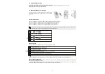
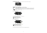
14.1) FIRST START OF ET-DSEL DIGITAL PROGRAMMER
Power the ETERNA 90 operator by mains voltage, the control unit buzzer emits some quick, short
beeps.
!
Language selection is shown on the display of ET-DSEL digital programmer;
!
use the
F2
and buttons to move arrow to the desired language.
!
Press EXIT button to exit “Language” section and enter “Serial communication setups”
section, as described under para. 14.3.
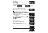
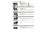
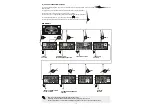
Power the ETERNA 150 operator by mains voltage, the
control unit buzzer emits some quick, short beeps.
ET-DSEL programmer automatically detects the
presence of operator electronic control unit (fig. A) and
stores the board serial code
ET-LOGIC-B (fig. B).
When acquisition of serial code is completed, the
display must show the closed padlock symbol on
number 1 and the open padlock symbol on the ?, if a
single ETERNA 90 operator is connected (fig. C),
fig.A
fig.B
fig.C
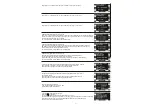
If the ET-DSEL digital programmer is connected to two
ETERNA 90 operators to manage two automatic doors,
instead, once serial code acquisition is completed the
closed padlock symbol must be displayed on number 1
and on number 2 (fig. D)
Press EXIT button to exit “Serial communication
setups” section and enter the general programming
menu.
Follow chapter 14.1 only if ET-DSEL digital programmer is new and powered for the first time.
Follow chapter 14.2 if digital programmer has already been used before.
Before powering the system set the S3 dip-switch of the ET-LOGIC-B logic board as specified in the table
14.2) SERIAL COMMUNICATION SETTINGS
fig.D
ET-LOGIC-B OPERATOR 1
ET-LOGIC-B OPERATOR 2
ON
OFF
S1 DIP 1