


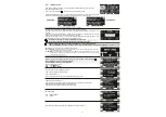


22
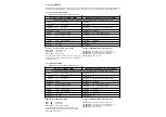
PART DESCRIPTION
LED
DL1 (40V)
= it displays the presence of 24V voltage at the switching power supply.
DL2 (E2) - DL3 (E1) - DL4 (E3)
= they display the signals coming from the encoder sensor.
DL6 - DL7
= battery status
Buzzer BZ1
= noise signaller.
MP1
= microcontroller A.
PS1
= START button. It performs door opening.
S1
= dip switch 1: operator number selection
1 OFF = OPERATOR "1"
1 ON = OPERATOR "2" (only in case a single ET-DSEL digital programmer is used to control two automatic doors)
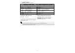
·
CONNECTOR J12:
Battery charger ET-BAT connection
·
CONNECTOR J5:
Battery connection.
·
CONNECTOR J8:
EN/RF1 radio receiver connector.
·
CONNECTOR J6:
Motor-encoder wiring connection.
·
CONNECTOR J4:
Electric lock 1 wiring connection (LOCK1).
·
CONNECTOR J3:
Electric lock 2 wiring connection (LOCK2).
·
CONNECTOR J2:
Optional UR24 module connection (OUT1).
·
CONNECTOR J1:
Optional UR24 module connection (OUT2).
·
JUMPER J10:
Operation selection electric LOCK2
POSITION 1 = CHEMIST’S FUNCTION (F04 = ON) or ANTIROLL FUNCTION FOR BOATS (P27 ≥ 01%)
POSITION 2 = electric lock bistable «EBSBIS»
·
CONNECTOR J11:
Digital programmer T-NFC connection
· TERMINAL BOARD M1 (F-N-GROUND)
230Vac 50-60Hz mains supply;
phase at terminal F, neutral at terminal N, ground connection at
terminal .
Ground the operator by connecting the ground cable from the line to
the Faston connector on the aluminum transom, connect the second
ground Faston on the transom to the ground terminal on the electronic
control unit.
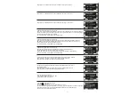
The line is protected by 2.5A fuse F1.
On the power supply mains, foresee an omni-polar switch/selector
with contact opening distance at least of 3 mm.
The power supply line must be protected against short circuit and
dispersion to ground.
Separate the 230Vac power supply line from the very-low voltage line
control unit relative to control and safety accessories.
·
TERMINAL BOARD M3 (Power supply of external
accessories)
24Vdc output for power supply to accessories (radars and sensors).
Max. load 500mA.
22
= Positive te24V.
21
= Negative terminal 0.
The presence of the output voltage is displayed by the DL1 led.
20
= TEST terminal for safety sensors prearranged with test function.
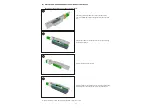
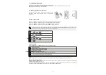
ELECTRIC CONNECTION DESCRIPTION
On the plastic side panels of the ETERNA 90 operator (part 1 in figure in para. 3) there is a hole that must be broken open, through which the
electric cables must be inserted.
Along the upper part of the aluminium transom, there are various fairleads (part 8 in the figure in para. 3) inside of which the cables should be
run.
The installer must prepare suitable fairleads on the side panel of the operator control unit for the passage of the cables and ensure wire
stability inside the operator control unit prior to the start-up of the automatic door, in order to prevent any contact between the electric cables
and the moving parts of the automatism.
M3
230Vac
M1
F1
2,5A
0
+24V
TEST(+)
20
0(-)
21
24V(+)
22
TEST FOR SAFETY
SENSORS
SENSORS POWER SUPPL
Y
F
N
0
0(-)
21