


Getting to know the machine
26
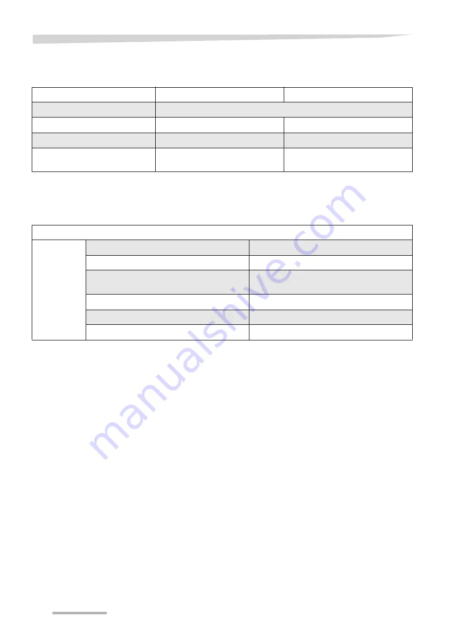
Weights
Necessary tractor
equipment
Work position [kg]
Transport position [kg]
Total weight
1.640
Load supported on sustainer
-
725
Load supported on lower link
-
615
Transport chassis axle load
-
Sustainer: 895
Lower link: 1,005
Output / connections
Minimum output of the tractor
35 kW (50 hp)
Lighting power supply
12 V, 7-pin plug socket ISO 1724
Hydraulic connections
1 x single-acting hydraulic control device
1 x double-acting hydraulic control device
Hydraulic pressure
150 - 210 bar
Maximum PTO shaft speed
540 rpm
Lower link
Fixable in height and laterally
Summary of Contents for Vicon Andex 724
Page 107: ...EC Conformity Declaration 107 ...
Page 108: ...EC Conformity Declaration 108 ...


