66
9. Connect network cables to the connectors on the module. If the
connected devices are working, the Link/Act LED will be ON.
Note: We suggest you to keep these removed module slot covers. It can be
use when these modules are removed in the future.
[ Remove Modules from the Switch at Front Panel ]
1. Turn off the switch first.
2. Loosen the screws of the module.
3. Remove the module slowly from the module slot.
4. Put on the module cover and fix it to the switch by driving its screws.
5. Power ON the switch.
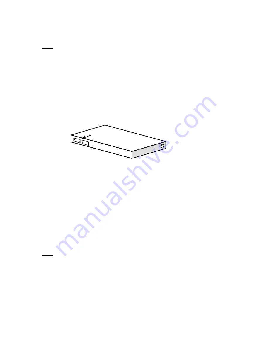
-- Modules at Rear Side (for 24+2G model) --
[ Adding Modules to the Switch at Rear Panel ]
1. Turn off the switch first.
2. Loosen the screws of the cover on the module slot.
3. Remove the cover on the module slot.
4. Follow the rails on both sides of the module slot to slide in the module
slowly.
5. Push the module firmly to make the module connecting well with the
connector in the switch.
6. Drive the screws to fix the module to the switch firmly.
7. Power ON the switch.
8. Connect network cables to the connectors on the module. If the
connected devices are working, the Link/Act LED will be ON.
Note: We suggest you to keep these removed module slot covers. It can be
use when these modules are removed in the future.
[ Remove Modules from the Switch at Front Panel ]
1. Turn off the switch first.
2. Loosen the screws of the module.
3. Remove the module slowly from the module slot.
4. Put on the module cover and fix it to the switch by driving its screws.
Rear Side
Module Slot
Summary of Contents for KS-2300
Page 1: ...KS 2300 KS 2600 Intelligent Switch User s Guide ...
Page 9: ...3 screws to mount the hub onto the standard EIA 19 inch rack ...
Page 12: ...6 ...
Page 15: ...9 Restore Default Settings Restore the factory default settings Reboot Reboot the switch ...
Page 69: ...63 Workgroup Power User Workgroup FS FS Switch Switch Gigabit Connection ...
Page 73: ...67 5 Power ON the switch ...
Page 76: ...70 ...


