background image

 PROFIBUS SETTINGS 

4

35

VFC 200

www.krohne.com

06/2019 - 4005059401 - AD VFC200 PB-PA R01 en

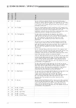
C4.3.2 Function

This parameter governs the behaviour of the totalization.

Setting:

Absolute Total: Arithmetic integration of the incoming rate values.

Incremental Total: Totalization of positive incoming rate values only.

Decremental Total: Totalization of negative incoming rate values only.

Stop: Totalization is stopped.

All As Positive: All incoming rates will be handled as positive values.

All As Negative: All incoming rates will be handled as negative values.

C4.3.3 Measurement

Setting:

Volume; Norm. Volume; Mass; Gross Energy; Net Energy

C4.3.4 Unit

Setting:

m

³

; L; hL; in

³

; ft

³

; gal; IG; bbl; Nm

³

; NL; Sft

³

; Sm

³

; SL; g; kg; T; lb; oz; J; kJ; 

MJ; kW*h; Mcal; BTU

C4.3.5 Preset Value

Preset value of the totalizer.

C4.3.6 Reset Totalizer?

Setting:

No; Yes

C4.3.7 Error Behavior

This parameter governs the behaviour of the totalizer during the occurrence 

of input values with BAD status.

Setting:

Ignore Error: Totalization is continued using the input values despite the 

BAD status. The status is ignored.

Stop Totalizer: Totalization is stopped during occurrence of BAD status of 

incoming values.

Hold Meas. Value: Totalization is continued based on the last incoming value 

with GOOD status before the first occurrence of BAD status.

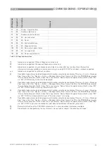
C4.4 FB Totalizer 2

C4.4.1 Set

Starts / stops the totalizer and defines its value if stopped.

Setting:

Totalize: Totalizing is started / is in progress (Normal operation of the 

totalizer).

Reset: Totalizing is stopped, 0.0 is assigned to the totalizer.

Preset: Totalizing is stopped, the preset value is assigned to the totalizer.

C4.4.2 Function

This parameter governs the behaviour of the totalization.

Setting:

Absolute Total: Arithmetic integration of the incoming rate values.

Incremental Total: Totalization of positive incoming rate values only.

Decremental Total: Totalization of negative incoming rate values only.

Stop: Totalization is stopped.

All As Positive: All incoming rates will be handled as positive values.

All As Negative: All incoming rates will be handled as negative values.

C4.4.3 Measurement

Setting:

Volume; Norm. Volume; Mass; Gross Energy; Net Energy

C4.4.4 Unit

Setting:

m

³

; L; hL; in

³

; ft

³

; gal; IG; bbl; Nm

³

; NL; Sft

³

; Sm

³

; SL; g; kg; T; lb; oz; J; kJ; 

MJ; kW*h; Mcal; BTU

C4.4.5 Preset Value

Preset value of the totalizer.

C4.4.6 Reset Totalizer?

Setting:

No; Yes

C4.4.7 Error Behavior

This parameter governs the behaviour of the totalizer during the occurrence 

of input values with BAD status.

Setting:

Ignore Error: Totalization is continued using the input values despite the 

BAD status. The status is ignored.

Stop Totalizer: Totalization is stopped during occurrence of BAD status of 

incoming values.

Hold Meas. Value: Totalization is continued based on the last incoming value 

with GOOD status before the first occurrence of BAD status.

Function

Setting / Description

Summary of Contents for VFC 200

Page 1: ...US PA PROFIBUS PA PROFIBUS device with MBP Physical Interface and PA Profile 3 02 2 0 2_ _190111 VFC 200 VFC 200 VFC 200 VFC 200 Supplementary Instructions Supplementary Instructions Supplementary Ins...

Page 2: ...Summary 12 3 Commissioning Operation 13 3 1 Configuration of cyclic data transfer 13 3 2 Cyclic data 13 3 2 1 Input data 13 3 2 2 Output data 19 3 3 Diagnosis 20 3 3 1 Mapping of DIAGNOSIS_EXTENSION b...

Page 3: ...ower off the signal converter immediately after manual change of parameter values Please wait approx 10 seconds before you switch off the signal converter after you have done both a parameter download...

Page 4: ...iver Version Model name 01 19 Signal converter with MBP interface PA Profile 3 02 2 0 2_ _190111 Simatic PCS7 other SPS of other manufact HW Config other Software of other SPS manufact GSD manuf speci...

Page 5: ...work As a rule the PROFIBUS PA segment is connected to a segment coupler which among other things carries out the conversion to the PROFIBUS DP bus line It should be mentioned that the segment coupler...

Page 6: ...will operate without an additional power supply connected For a detailed description of the electrical connections please refer to the standard handbook Refer also to the PROFIBUS PA user and installa...

Page 7: ...ion Software GSD GSD file on CD ROM or from internet site Supported GSD KR014541 GSD PA139741 GSD Device profile PROFIBUS PA Profile 3 02 conformance class B compact Address range 0 126 default 126 0...

Page 8: ...BUS DP communication network Supplementary files e g ___ bmp and ___ dib contain icons which will represent the PROFIBUS devices in the view of the bus configuration system master system The files mus...

Page 9: ...u menu item Identification No A14 C3 3 1 2 The following settings are supported Automatic adaptation mode factory setting Manufacturer specific Ident number VFC200 4541 hex Profile specific Ident numb...

Page 10: ...his GSD file provides complete functionality of the PROFIBUS PA device All function blocks are available for cyclic data transfer Slot Description Function Block types Default unit 1 Volume Flow AI FB...

Page 11: ...ts of the signal converter should be transferred cyclically to the master This is performed by a bus configuration tool e g HW Config for PC S7 from Siemens This tool offers specific functions as foll...

Page 12: ...lector Ident Number GSD File Status Automatic adaptation mode 4541 KR014541 GSD Classic Condensed 9741 PA139741 GSD 1 Classic Manufacturer specific Ident Number 4541 KR014541 GSD Classic Condensed Pro...

Page 13: ...function block data following this empty module will move up one position 3 2 Cyclic data In a PROFIBUS network cyclic data is described from the point of view of the master Therefore input data is tr...

Page 14: ...ntenance Nevertheless Classic Status and Diagnosis is still available for this device It is implemented for backwards compatibility to older devices or PLC systems which do not support Condensed Statu...

Page 15: ...e not supported Table 3 2 Coding for Condensed Status Quality Quality substatus Limits Gr Gr QS QS QS QS Qu Qu 27 26 25 24 23 22 21 20 0 0 0 0 0 0 0 0 non specific not provided by the device 0 0 1 0 0...

Page 16: ...use it for process control The Quality Substatus and Limit bits will be used for further diagnostics or limit checking Quality Quality substatus Limits Gr Gr QS QS QS QS Qu Qu 27 26 25 24 23 22 21 20...

Page 17: ...QS QS QS Qu Qu 27 26 25 24 23 22 21 20 0 0 0 0 0 0 non specific 0 0 0 0 0 1 configuration error 0 0 0 0 1 0 not connected 0 0 0 0 1 1 device failure 0 0 0 1 0 0 sensor failure 0 0 0 1 0 1 no communic...

Page 18: ...for process control The Quality Substatus and Limit bits will be used for further diagnostics or limit checking Quality Quality substatus Limits Gr Gr QS QS QS QS Qu Qu 27 26 25 24 23 22 21 20 1 0 0 0...

Page 19: ...r is reset to 0 0 and remains at this value until SetTot is reset to 0 If the value of SetTot changes from 1 to 0 the totalizer starts counting from 0 0 SetTot 2 Totalizer is set to the value defined...

Page 20: ...g within the GSD file It represents the position in the device related diagnostic field of the Slave_Diag service Bit Number Supported Description Remedy 16 Yes Error appears 17 Yes Error disappears 2...

Page 21: ...to measurement mode 6 57 3 C Configuration Configuration related Function check running E g the measurement values may be simulated values for a currently performed check The related output values are...

Page 22: ...em s 5 if the problem s cannot be fixed contact the service department of the manufacturer with an indication of the problem s 68 3 S Process Process related fault s detected E g the device may be ope...

Page 23: ...ailable readout more detailed diagnosis information using the device display Device Errors Message View menu C6 4 1 or Device Errors Message History View menu C6 4 2 or the PROFIBUS parameter Device S...

Page 24: ...information of the for detailed information refer to chapter Status messages and diagnostic information of the for detailed information refer to chapter Status messages and diagnostic information of...

Page 25: ...osis details to Show action only or Show all Have a look at section Diagnosis details All Event groups with at least one Single event currently existing will be displayed All Single events belonging t...

Page 26: ...5 Event group 29 F Configuration X X 6 Event group 30 F Electronics X X 7 Event group 31 F Sensor X X 1 0 Event group 16 M Process X X 1 Event group 17 M Configuration X X 2 Event group 18 M Electron...

Page 27: ...ntenance demanded demanded demanded demanded 41 will be set additionally If e g the diagnosis event bit of Event group F F F F Sensor Sensor Sensor Sensor 63 has been set both the diagnosis event bit...

Page 28: ...Process X X 5 Event group 29 F Configuration X X 6 Event group 30 F Electronics X X 7 Event group 31 F Sensor X X 1 0 Event group 16 M Process X X 1 Event group 17 M Configuration X X 2 Event group 1...

Page 29: ...Config Operation Info fixed to Information If using the DTM or EDD DTM or EDD DTM or EDD DTM or EDD you are able to choose one of the following settings DTM Enter menu Parameters Input Diagnostics ED...

Page 30: ...maintenance OR UNCERTAIN maintenance demanded M Maintenance required diagnosis DIA_MAINTENANCE Maintenance required 37 status GOOD maintenance required C Function check diagnosis DIA_FUNCTION_CHECK F...

Page 31: ...ilter Diagnosis filter Within the Diagnosis filter area all Single Events will be displayed which might be filtered Unmark all check boxes of Single Events that shall be ignored Transfer new filter se...

Page 32: ...og Input 1 B2 23 FB Analog Input 2 Displays current value of Analog Input 2 B2 24 FB Analog Input 3 Displays current value of Analog Input 3 B2 25 FB Analog Input 4 Displays current value of Analog In...

Page 33: ...Vortex Frequency Velocity Specific Enthalpy Specific Heat Capacity Reynolds Number C3 3 4 2 Time Constant Set time constant for this function block C3 3 4 3 Error Behavior Defines the behaviour of th...

Page 34: ...or OUT has the wrong calculated value and status Bad as calculated C3 3 7 4 Replacement Value Defines the value that replaces the measured value at this function block in case of an error C3 3 8 FB An...

Page 35: ...et Starts stops the totalizer and defines its value if stopped Setting Totalize Totalizing is started is in progress Normal operation of the totalizer Reset Totalizing is stopped 0 0 is assigned to th...

Page 36: ...Select the variable for the third measurement line Setting Volume Flow Norm Volume Flow Mass Flow Gross Power Net Power FAD Temperature 1 Temperature 2 Pressure Density Vortex Frequency Velocity Spec...

Page 37: ...is not correct F_Electronics 30 15 FB PA Runtime Data Failure Runtime data failure occurred in FB Main F_Electronics 30 14 FB PA Runtime execution failure Runtime execution failure occurred in FB Main...

Page 38: ...13 31 FB Totalizer Stopped At least one Totalizer operating in FB Main is stopped I_Info Cfg_Op_Info 13 30 FB Write Protection Active Write protection is activated by FB Main by parameter or hardware...

Page 39: ...sure value has initial status External pressure sensor value has status Initial Table 4 5 Status messages and diagnostic information NAMUR groups fixed level NAMUR groups configurable level Group no E...

Page 40: ...ervices Head Office KROHNE Messtechnik GmbH Ludwig Krohne Str 5 47058 Duisburg Germany Tel 49 203 301 0 Fax 49 203 301 10389 info krohne com KROHNE 06 2019 4005059401 AD VFC200 PB PA R01 en Subject to...

Reviews: