4
PROFIBUS SETTINGS
32
VFC 200
www.krohne.com
06/2019 - 4005059401 - AD VFC200 PB-PA R01 en
Detailed description of special settings concerning the PROFIBUS features easily operated via
the local display menu of the signal converter (refer to the following sections). For a detailed
description of the menus and functions in general please refer to the standard product
documentation of the signal converter.
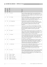
4.1 Menu "A Quick Setup"
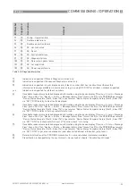
4.2 Menu "B Test"
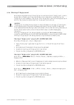
4.3 Menu "C Setup"
Function
Setting / Description
A14 Identification Number
Unique Profibus ID number
A15 Station Address
Profibus station address
A12.15 Cluster 15
Menu listing all Profibus unit settings related to cluster check 15
A15.15.1 FB Analog Output Unit
Select Analog Output unit (cf. C3.3.8.2)
A15.15.2 FB Totalizer 1 Unit
Select Totalizer 1 unit (cf. C4.3.4)
A15.15.3 FB Totalizer 2 Unit
Select Totalizer 2 unit (cf. C4.4.4)
Table 4-1: Description of menu "A Quick Setup"
Function
Setting / Description
B2 Actual Values
B2 Actual Values
B2 Actual Values
B2 Actual Values
B2.22 FB Analog Input 1
Displays current value of Analog Input 1
B2.23 FB Analog Input 2
Displays current value of Analog Input 2
B2.24 FB Analog Input 3
Displays current value of Analog Input 3
B2.25 FB Analog Input 4
Displays current value of Analog Input 4
B2.26 FB Analog Input 5
Displays current value of Analog Input 5
B2.27 FB Totalizer 1
Displays current value of Totalizer 1
B2.28 FB Totalizer 2
Displays current value of Totalizer 2
Table 4-2: Description of menu "B Test"
Function
Setting / Description
C3 Communications
C3 Communications
C3 Communications
C3 Communications
C3.3 Profibus PA
Profibus configuration submenu.
C3.3.1 Physical Block
Description of the physical block.
C3.3.1.1 Tag
Tag of the device.
C3.3.1.2 Identification Number
Setting:
Profile: Profile specific identification number (9741 hex);
Manufacturer: Manufacturer specific identification number (4541 hex);
Automatic: Automatic adaptation mode
C3.3.1.3 Station Address
Selects the address of the device at the PROFIBUS interface.
C3.3.2 TB Flow
Transducer Block configuration submenu.
C3.3.2.1 Low Flow Cutoff
The volume flow and further measuring values are set to zero if its absolute
value is less than the "Low Flow Cutoff" value.
C3.3.2.2 LFC Hysteresis
Defines the hysteresis used during calculation of the volume flow "Low Flow
Cutoff" function.


