


ELECTRICAL CONNECTIONS
3
31
OPTISONIC 1400
www.krohne.com
10/2016 - 4005626301 - QS OPTISONIC 1400 R01 en
3.3 Power supply
Electrical connection -
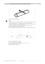
Figure 3-4: Connect the cables in the connection box after the connection of the sensor wiring.
INFORMATION!
Connect the cable on connector with similar numeral marking
WARNING!
When this device is intended for permanent connection to the mains.
It is required (for example for service) to mount an external switch or circuit breaker near the
device for disconnection from the mains. It shall be easily reachable by the operator and marked
as the disconnecting the device for this equipment.
The switch or circuit breaker and wiring has to be suitable for the application and shall also be in
accordance with the local (safety) requirements of the (building) installation
(e.g. IEC 60947-1 / -3)
INFORMATION!
For devices used in hazardous areas, additional safety notes apply; please refer to the Ex
documentation.
INFORMATION!
The power terminals in the terminal compartments are equipped with additional hinged lids to
prevent accidental contact.
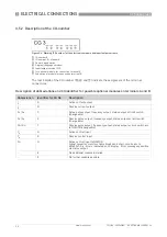
1
100...230 VAC (-15% / +10%), 22 VA
2
24 VDC (-55% / +30%) 12 W
3
24 VAC/DC (AC: -15% / +10%; DC: -25% / +30%), 22 VA or 12 W


