


2
INSTALLATION
26
OPTISONIC 1400
www.krohne.com
10/2016 - 4005626301 - QS OPTISONIC 1400 R01 en
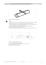
2.16.7 Alignment of the transducers
Both the transducers of a path must
“
see
”
each other. It means that the transducer windows
must be pointed at each other.
The position of the transducer window is indicated at the end of the stem of the transducer (close
to the conduit fitting) by a red line
•
Fill the pipe with water
•
Switch on the converter
•
Check for signals (velocity of sound measurement)
•
Rotate each individual transducer stem with a wrench until the gain is minimal
(menu item B2.5 )
•
Lock the position of the stem by tightening the fixation screw with an Allen key
For permanent fixation of the transducer position, the position of the stem can be secured by
welding it to the fixation plate
i
The OPTISONIC 1000 is now installed and ready for connection to the signal converter.
Figure 2-31: Transducer alignment
1
Red line at the end of the stem of the transducer (close to the conduit fitting)
2
Transducer windows facing each other
3
Pipe-line wall


