ELECTRICAL CONNECTION INDICATOR M10
5
27
BW25
www.krohne.com
10/2008 • 4000432301 MA BW25 R01 en
5.4 M10 switching outputs B1 and B2
The switching outputs are electrically isolated from each other and from the analog output.
Switching outputs B1 and B2 can be implemented electrically with two attachment types:
•
NAMUR switching output - Ri approx. 1kOhm
•
Low-resistance switching output with PNP technology
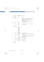
Switching values
Switching values
Switching values
Switching values
CAUTION!
The switching outputs can only be operating if the power supply is applied to terminals I+ and I-.
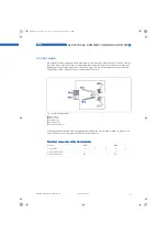
Figure 5-3:
Indicator M10 - switching outputs
1
NAMUR terminal connection
2
Isolation switching amplifier
3
PNP technology terminal connection
4
Power supply
5
Load
NO contact
NC contact
NAMUR
OC
NAMUR
OC
I [mA]
Switching value
reached
< 1
< 1
> 3
max 100
Switching value
not reached
> 3
max. 100
< 1
< 1
MA_BW25_R01_en_PRT.book Page 27 Thursday, October 30, 2008 3:49 PM


