7
MENU INDICATOR M10
40
BW25
www.krohne.com
10/2008 • 4000432301 MA BW25 R01 en
7.3 Menu explanations
Level
Designation
Selection/input
options
Explanation
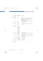
1.1.1
OUTPUT B1
INACTIVE
LEV.VALUE B1
Level value switching point. A numeric value between 0.0 ...
100% of the level value can be set. If the current level value
exceeds this set switching point, then output B1 is
activated.
Note
Note
Note
Note
The function NC or NO can be selected using menu 3.3.
1.1.2
OUTPUT B1
HYST.B1
Hysteresis setting for the level value switching point. Value
range 0...switching point. Example, if a switching value of
200 is set under 1.1.1, then a hysteresis value of 0...200 can
be set here. If the value 0 is entered here, then this output
does not have hysteresis. If the value 20 is input, then the
output works as follows: it switches when the current value
exceeds a value of 200.
3
If the current level value is below
the hysteresis value of 180, then the switching output
returns to the normal state.
4
Note
Note
Note
Note
To invert the operating method, use menu 3.3 to set the
output from NO
1
to NC
2
or vice versa. This function is
not activated on the counter switching point.
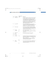
1.2.1
OUTPUT B2
INACTIVE
LEV.VALUE B2
See LEV.VALUE B1
1.2.2
OUTPUT B2
HYST.B2
See HYST. B1
1.3
DISPLAY
LEVEL
%
LEVEL & %
1.4
TIME CONST.
Setting : 1 ... 20 seconds
Note
Note
Note
Note
The settable time constant affects the current output and
the displayed current level. It thus allows attenuated
depiction when the display is not calm. If the current level
is polled via HART communication, then the transferred
measured value is dependent on the time constant.
MA_BW25_R01_en_PRT.book Page 40 Thursday, October 30, 2008 3:49 PM


