5
ELECTRICAL CONNECTION INDICATOR M10
24
BW25
www.krohne.com
10/2008 • 4000432301 MA BW25 R01 en
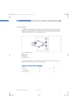
5.2 M10 Electrical connection and functions
The display can be removed after the housing lid has been unscrewed. The connection terminals
have a spring locking system.
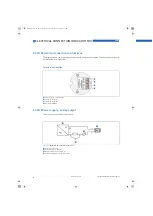
5.3 M10 Power supply - analog output
The electrical connection is polarized.
Terminal connection
1
Power supply - analog output
2
Switching output B1
3
Switching output B2
4
Not used for BW25
Figure 5-1:
Indicator M10 - terminal connection I
1
Terminal connection
2
Power supply 16...32VDC
3
Measurement signal 4...20 mA
4
External load, HART
TM
communication
MA_BW25_R01_en_PRT.book Page 24 Thursday, October 30, 2008 3:49 PM

