4
ELECTRICAL CONNECTION INDICATOR M9
20
BW25
www.krohne.com
10/2008 • 4000432301 MA BW25 R01 en
4.3 Electrical signal output ESK
The connecting terminals of the ESK have a pluggable design and can be removed in order to
connect the lines.
The circuitry for connection to other devices such as digital evaluator units or process control
equipment must be designed with especial care. In some circumstances internal connections in
these devices (e.g. GND with PE, ground loops) may lead to impermissible voltage potentials,
which can compromise the function of the device itself or a connected device. In such cases a
protected extra-low voltage (PELV) is recommended.
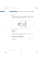
Figure 4-5:
ESK2A connection
1
ESK2A current transmitter
2
Power supply 12...30VDC
3
Measurement signal 4...20 mA
4
External load, HART
TM
communication
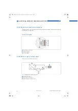
Figure 4-6:
ESK2A connection with electrical isolation
1
Terminal connection
2
Converter supply isolator with electrical isolation
3
Power supply (see supply isolator information)
4
Measurement signal 4...20mA
5
External load, HART
TM
communication
MA_BW25_R01_en_PRT.book Page 20 Thursday, October 30, 2008 3:49 PM


