5
ELECTRICAL CONNECTION INDICATOR M10
28
BW25
www.krohne.com
10/2008 • 4000432301 MA BW25 R01 en
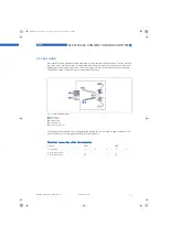
Switching capacity of B1 and B2 with PNP technology
Due to the PNP technology and the associated protective elements, there is a voltage drop Uv for
the load to be operated.
Figure 5-4:
Indicator M10 - Breaking capacity of B1 and B2
1
Max. switching current Y1 [mA]
2
Minimum load impedance Y2 [ohm]
3
Power supply
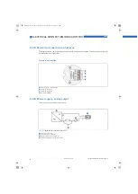
Figure 5-5:
Indicator M10 - power loss of B1 and B2
1
Load impedance 100 Ohm
2
Load impedance 1000 Ohm
3
Power loss
4
Power supply
MA_BW25_R01_en_PRT.book Page 28 Thursday, October 30, 2008 3:49 PM


