


Operation & Installation Manual V12-V6 2010-05-31.doc
31/05/2010
28/60
•
The power supply to the I/O card should be a NEC class 2 power supply (max 100VA,
24 VDC, IEC 61010-1, Clause 6.3.1 & 6.3.2)
•
The Protective Conductor terminal of the I/O compartment can be used for cable
shielding.
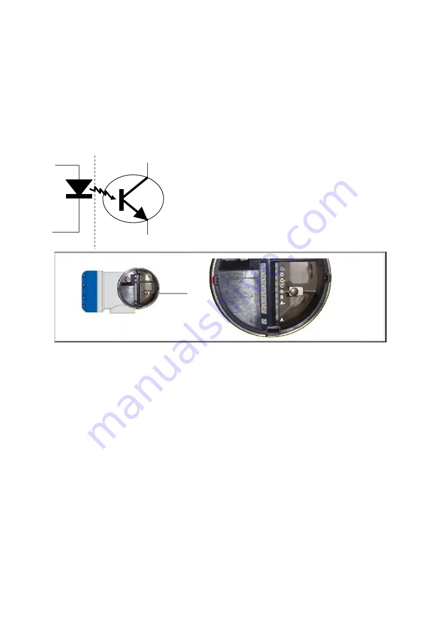
The digital outputs are connected to the screw terminals in compartment a.
The terminal marked with A, B, C and D is connected to the collector of the (NPN) transistor
acting as a switch, the terminal with the A-, B-, C- and D- sign is connected to the emitter of
the transistor.
Figure 5-2: Digital & frequency outputs
Four digital output signals are available. Each output can be defined as a pulse or frequency
output or as a status output. (Remark: A+ is not used)
5.3.2.1. Pulse/Frequency output,
Default the first digital I/O connection is set as a pulse/frequency output, having a frequency
proportional to the volume flow rate (actual volume: under process conditions). It is possible
to assign another variable to control this output (defined by means of parameter settings, see
section 2.4.5).
5.3.2.2. Status outputs.
Default the next three digital I/O connections are defined as status outputs (Data not valid,
Fail unreliable and Reverse flow). However the function of these outputs can be programmed
to various alarms or status signals. One of the status outputs may be programmed to a
second pulse output, having the same frequency as the first pulse output, however the phase
difference can be set to either 0, 90, 180 or 270 degrees.
5.3.2.3. Emulation of a turbine meter
If the ultrasonic flow meter should emulate a turbine meter. The following set up and settings
can be implemented:
•
A/A-: Frequency output related to the line flow
A, B, C, D
A-, B-, C-, D-


