P/N: 2900-300932 Rev 3
www.KramerAV.com
USER MANUAL
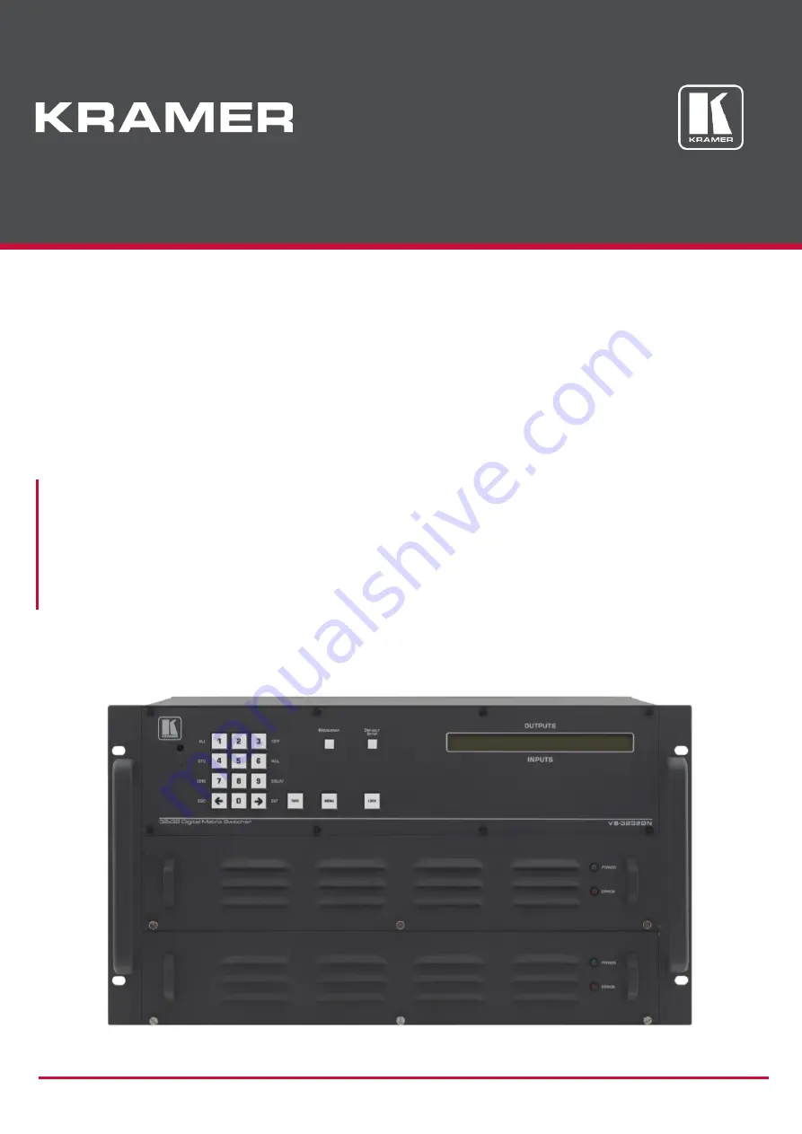
MODEL:
VS-3232DN-EM 4x4 to 32x32 Modular Multi-Format Managed Digital Matrix Switcher
Page 1: ...P N 2900 300932 Rev 3 www KramerAV com USER MANUAL MODEL VS 3232DN EM 4x4 to 32x32 Modular Multi Format Managed Digital Matrix Switcher ...
Page 2: ...32 43 Defining the DTAxr IN4 F32 DTAxr OUT4 F32 44 Defining the HDBT IN4 F32 HDBT OUT4 F32 47 Defining the H IN4 F32 H OUT4 F32 50 Defining the HAD IN4 F32 HAD OUT4 F32 51 Defining the HAA IN4 F32 HAA OUT4 F32 53 Defining the HDCP IN4 F32 HDCP OUT4 F32 55 Defining the DGKat IN4 F32 DGKat OUT4 F32 56 Defining the F670 IN4 F32 F670 OUT4 F32 58 Defining the F610 IN4 F32 F610 OUT4 F32 59 Defining the ...
Page 3: ...Kramer Electronics Ltd VS 3232DN EM Contents ii Protocol 3000 96 Understanding Protocol 3000 Commands 97 Protocol 3000 Syntax 97 Protocol 3000 Commands 98 Using the Packet Protocol 122 ...
Page 4: ...ration is shown with 32 DVI inputs and 32 DVI outputs as a representation only The following cards are available and may be mixed in the same chassis UHD IN4 F32 UHD OUT4 F32 see Defining the UHD IN4 F32 UHD OUT4 F32 on page 39 UHDA IN4 F32 UHDA OUT4 F32 see Defining the UHDA IN4 F32 UHDA OUT4 F32 on page 39 DT IN4 F32 DT OUT4 F32 see Defining the DT IN4 F32 DT OUT4 F32 on page 47 DTAxr IN4 F32 DT...
Page 5: ...you Unpack the equipment carefully and save the original box and packaging materials for possible future shipment Review the contents of this user manual Go to www kramerav com downloads VS 3232DN EM to check for up to date user manuals application programs and to check if firmware upgrades are available where appropriate Achieving the Best Performance To achieve the best performance Use only good...
Page 6: ...lectronic Equipment WEEE Directive 2002 96 EC aims to reduce the amount of WEEE sent for disposal to landfill or incineration by requiring it to be collected and recycled To comply with the WEEE Directive Kramer Electronics has made arrangements with the European Advanced Recycling Network EARN and will cover any costs of treatment recycling and recovery of waste Kramer Electronics branded equipme...
Page 7: ...and TP 574 as long as the devices are within 90m 270ft of each other The Power Connect feature applies as long as the cable can carry power and the distance does not exceed 90m on standard CAT 5 cable For longer distances a heavier gauge cable should be used a TP cable is still suitable for the video audio transmission but not for feeding the power at these distances Overview The Kramer VS 3232DN ...
Page 8: ...als from compatible Kramer transmitters automatically converts between available infrastructure options and sends the signals to compatible Kramer receivers Max Data Rate 10 2Gbps 3 4Gbps per graphic channel when using compatible cards HDTV Compatible HDCP Compliant With DVI HDCP HDMI F670 HDBaseT HDMI with audio and DGKat modules HDMI Support DGKat Signal Integration Kramer s unique technology fo...
Page 9: ...r serial controller Ethernet over a LAN The infrared remote control transmitter future Kramer Network enterprise management platform The VS 3232DN EM is a sophisticated device but has nevertheless been designed to be simple to operate using an intuitive front panel keypad For details of how to route inputs to outputs see Switching Actions on page 21 The VS 3232DN EM is housed in a 19 rack mountabl...
Page 10: ... the current setup in a preset After pressing the MENU button this button lights and is enabled 4 ALL Press to connect an input to all outputs After pressing the MENU button this button lights and is enabled 5 OFF Press to turn off an output After pressing the MENU button this button lights and is enabled 6 RCL Press to recall a preset After pressing the MENU button this button lights and is enabl...
Page 11: ... see Using the Configuration Menus on page 24 Press again to enter the configuration menu see Using the Config Menu on page 28 When in a Menu press to cycle through the menu items 16 LOCK Button Press and hold for approximately 2 sec to lock unlock the front panel buttons see Locking the Front Panel Buttons on page 23 17 Power Supply Supplies power to the device 18 19 POWER LED Lights green when p...
Page 12: ... Card on page 36 30 RESOLUTION DIP switches Set the resolution for video generated by the Test module see Setting the Resolution of the Generated Video on page 36 31 RS 232 9 pin D sub Port Connect to a PC or remote controller see Connecting to the VS 3232DN EM via RS 232 on page 15 and perform firmware upgrade of the device and compatible input output cards see Upgrading the VS 3232DN EM Firmware...
Page 13: ...DN EM Introduction 10 Feature Function 36 Test Module DVI Molex 24 pin Video Connector Connect to one of the relevant video inputs outputs to aid in troubleshooting see Using the Test Module to Troubleshoot Video Problems on page 69 ...
Page 14: ... VS 3232DN EM before connecting any cables or power Warning Ensure that the environment e g maximum ambient temperature air flow is compatible for the device Avoid uneven mechanical loading Appropriate consideration of equipment nameplate ratings should be used for avoiding overloading of the circuits Reliable earthing of rack mounted equipment should be maintained To mount the VS 3232DN EM on a r...
Page 15: ...ring on page 14 Exactly the same principles apply to installations using other card types To connect the VS 3232DN EM as illustrated in the example in Figure 4 do the following 1 Connect up to 32 DVI video sources for example computer graphics sources 2 Connect up to 32 DVI video acceptors for example a DVI display and a DVI LCD display 3 If required connect a PC or remote controller to the RS 232...
Page 16: ...Kramer Electronics Ltd VS 3232DN EM Connecting the VS 3232DN EM 13 Figure 4 Connecting the VS 3232DN EM ...
Page 17: ...link card provides two physical ports which causes the loss of two numbers in the numbering sequence of that card only A sample numbering is shown in Figure 5 Figure 5 Sample Port Numbering Diagram Actual Port Number 1 IN 1 IN 2 IN 3 IN 4 2 IN 5 IN 6 3 IN 9 IN 10 IN 11 IN 12 4 OUT 1 OUT 2 OUT 3 OUT 4 5 OUT 5 OUT 6 OUT 7 OUT 8 6 OUT 9 OUT 10 There is no IN 7 IN 8 OUT 11 or OUT 12 because these slot...
Page 18: ...EDID input 8 VS 3232DN EM Output port 8 has been assigned to all EDID outputs VS 3232DN EM Input ports Figure 6 EDID Numbering Assignment Connecting to the VS 3232DN EM via RS 232 You can connect to the VS 3232DN EM via an RS 232 connection using for example a PC Note that a null modem adapter connection is not required To connect to the VS 3232DN EM via RS 232 Connect the RS 232 9 pin D sub rear ...
Page 19: ...nnect the Ethernet port of the VS 3232DN EM directly to the Ethernet port on your PC using a crossover cable with RJ 45 connectors This type of connection is recommended for identifying the VS 3232DN EM with the factory configured default IP address After connecting the VS 3232DN EM to the Ethernet port configure your PC as follows 1 Click Start Control Panel Network and Sharing Center 2 Click Cha...
Page 20: ...ol Properties window relevant to your IT system appears as shown in Figure 8 or Figure 9 Figure 8 Internet Protocol Version 4 Properties Window Figure 9 Internet Protocol Version 6 Properties Window 6 Select Use the following IP Address for static IP addressing and fill in the details as shown in Figure 10 ...
Page 21: ... 1 255 excluding 192 168 1 39 that is provided by your IT department Figure 10 Internet Protocol Properties Window 7 Click OK 8 Click Close Connecting the Ethernet Port via a Network Hub or Switch You can connect the Ethernet port of the VS 3232DN EM to the Ethernet port on a network hub or using a straight through cable with RJ 45 connectors ...
Page 22: ...d within the Selector Buttons area see Defining the VS 3232DN EM 4x4 to 32x32 Modular Multi Format Managed Digital Matrix Switcher on page 7 This numeric keypad lets you enter both the output and input numbers as well as various numeric configuration values see Using the Selector Buttons on page 20 When the unit is powered on the last matrix setup that was used is loaded Use either the setup recal...
Page 23: ...isconnected from any input note that the corresponding inputs in the second line are blank 06 07 08 09 10 11 12 13 12 08 10 14 13 06 The ESC button is used to cancel an operation without affecting the current status For example if you enter an incorrect number by mistake press the ESC button to cancel the operation At any stage if no button is pressed within approximately 15 seconds the automatic ...
Page 24: ...Switching Action Actions only require confirmation when the device is in the Confirm mode To confirm a switching action 1 Using the numeric keypad enter an output input combination The TAKE button flashes 2 Press the flashing TAKE button to confirm the action The action is confirmed and the TAKE button lights Switching Actions This section describes how to Switch one input to one output see Switch...
Page 25: ... output input combination The TAKE button flashes 2 Enter additional output input combinations The LCD display can show up to five pending actions although the batch is not limited to five actions as follows 09 06 05 07 In this example input 9 is set to switch to output 6 and input 5 is set to switch to output 7 3 After entering all output input combinations press the flashing TAKE button to confi...
Page 26: ... To recall the default setup 1 Press DEFAULT SETUP The DEFAULT SETUP button flashes and the following message is displayed recall DEFAULT setup press FLASHING button to confirm 2 Press DEFAULT SETUP The following message is displayed all Setups and Connections change press TAKE to confirm The TAKE button flashes 3 Press TAKE The default setup is recalled and the display reverts to the output input...
Page 27: ...AY to exit the Menu altogether At any point in the Menu only buttons that are active light or flash All the procedures in this section assume that you are starting the procedure from the standard operational output input display Using the Setup Menu The Setup Menu provides access to settings that are regularly changed and comprises the following options 1 inXX ALL switching one input to all output...
Page 28: ... TAKE The selected input is switched to all outputs The display reverts to the output input display showing that the selected input is switched to all outputs Setup Menu 3 outXX OFF Turning an Output Off This option turns an output off To turn an output off 1 Press MENU The Setup Menu options are displayed 2 Press 3 OFF on the numeric keypad see Figure 2 The following is displayed out__ OFF 3 Usin...
Page 29: ... storage To assign an EDID to between one and eight inputs 1 Press MENU The Setup Menu options are displayed 2 Press 7 EDID on the numeric keypad see Figure 2 The following is displayed SETUP EDID ENT to View EDID and Set EDID 3 Press ENT The current EDID matrix configuration is displayed 4 Using the numeric keys enter the input in which to store the EDID in this example 08 and enter the output in...
Page 30: ...9 DELAY on the numeric keypad see Figure 2 The output delay times display is shown 3 Using the numeric keys enter the output in this example 03 The following is displayed 01 02 03 04 05 06 07 08 DLY__ out03 4 Using the numeric keys enter the number of delay units 5 Press TAKE The selected output delay is set The display reverts to the output input display Setup Menu 4 store setup XX Storing the Se...
Page 31: ...is recalled The display reverts to the output input display Using the Config Menu The Config Menu provides access to configuration settings that are not regularly changed and comprises the following options Input signal detection display Config Menu Input Signal Detection Display on page 29 Input port parameter setting Config Menu Setting Input Port Parameters on page 29 Output load detection disp...
Page 32: ...puts and indicates on which of them signals have been detected To display a list of inputs that have detected signals 1 Press MENU twice The following message is displayed start configuration menu MENU to view setup ENT to change them 2 Press MENU The following is displayed IN 01 02 03 04 05 06 07 08 09 10 11 SIG o X o o o o X o o o X o indicates that a signal is detected and X indicates that no s...
Page 33: ... left and right arrow buttons 5 Press TAKE to enter the parameters list A message similar to the following is displayed with the relevant port number in place of 06 IN 06 SET 36 Reset SubBoard 6 To select the next parameter press the right arrow button see Using the Input Output Cards on page 39 for available parameters Or 7 To enter the selected parameter press TAKE The parameter options are disp...
Page 34: ...rs This option sets port specific parameters Ports that show an X have no parameters available to modify Ports that show an o have parameters available to modify The parameters that are available such as audio balance depend on the type of card installed and whether the card is an input or an output card see Using the Input Output Cards on page 39 for information on the input output cards and thei...
Page 35: ... parameters 11 Do one of the following Press BREAKAWAY to exit the Config Menu Wait approximately 15 seconds for the operation to time out Press MENU to exit to the parameter list Config Menu Store Default Setup This option lets you store the current setup as the default setup The default setup can be recalled at any time using the DEFAULT SETUP button see Recalling the Default Setup on page 23 Th...
Page 36: ...3 Press ENT to enter the Reset Submenu The following is displayed COMPLETELY MATRIX RESET 1 ALL outputs OFF 2 Factory default 4 Press 1 to turn off all outputs or 2 to perform a factory reset of all options Selecting option 2 to perform a factory default reset clears all setups options and configuration 5 Press TAKE and wait a few seconds The following is displayed Are you Absolutely sure Once mor...
Page 37: ...sing the Configuration Menus 34 2 Press MENU until the following is displayed Main Firmware Version 5 0 Front Firmware Version 5 0 3 Either Press BREAKAWAY to exit the Config Menu Wait approximately 15 seconds for the operation to time out ...
Page 38: ... output ports 1 Press ESC ENT and LOCK together The following is displayed Configuration Device 2 Press ENT The following is displayed Test Board 1 MaxInput 33 MaxOutput 33 The number of input and output ports can only be set in units of two for example 4 x 4 16 x 4 or 12 x 16 3 Using the numeric keys enter the number of input and output ports installed The TAKE button flashes 4 Press TAKE The num...
Page 39: ...tor BANDWIDTH PER CHANNEL 2 25Gbps TOTAL BANDWIDTH 6 75Gbps 3D PASS THROUGH Not Supported POWER CONSUMPTION 5W OPERATING TEMPERATURE 0 to 40 C 32 to 104 F STORAGE TEMPERATURE 40 to 70 C 40 to 158 F HUMIDITY 10 to 90 RHL non condensing DIMENSIONS 22cm x 18 8cm x 2cm 8 7 x 7 4 x 0 8 W D H PRODUCT WEIGHT 0 15 kg 0 33 lbs approx SHIPPING WEIGHT 0 3 kg 0 66 lbs approx STANDARD COMPLIANCE HDCP 1 4 SAFET...
Page 40: ...he Pattern of the Generated Video The Pattern button is used to set the pattern of generated video There are 32 available patterns Press the button repeatedly to cycle through the patterns Installing the Test Module By default the test module is installed in the configuration If you uninstalled the test module in the configuration it must be reinstalled before it can be used When installing the te...
Page 41: ...hat the test module is not installed 3 Using the numeric keys press 1 to indicate that the test module is installed The TAKE button flashes 4 Press TAKE 5 Increase the number of configured inputs and outputs by one see Configuring the Number of Installed Input and Output Ports on page 35 6 Power cycle the device The test module is now installed and may be used ...
Page 42: ...D OUT4 F32 cards feature ARC support EDID Capture Copies and stores the EDID from a display device Kramer Equalization and re Klocking Technology UHD IN4 F32 UHD OUT4 F32 Configuration The UHD IN4 F32 configuration table appears as follows UHD IN4 F32 Input Card Parameter Description Default HDCP Turn HDCP on and off 0 EN 1 DIS Note Analog audio is still transmitted when HDCP is disabled 0 Reset I...
Page 43: ... lbs approx STANDARD COMPLIANCE HDCP 1 4 HDMI 1 4 HDTV compatible SAFETY REGULATORY COMPLIANCE CE ENVIRONMENTAL REGULATORY COMPLIANCE Complies with appropriate requirements of RoHs and WEEE Defining the UHDA IN4 F32 UHDA OUT4 F32 The UHDA IN4 F32 is a four channel 4K60 4 2 0 HDMI with analog audio input card The UHDA IN4 F32 inputs four HDMI signals to the chassis with optional embedding de embedd...
Page 44: ...lected AUD Analog Analog audio from the 3 5mm mini jack is selected AUD Digital ST Selects the manner in which the analog audio port functions 0 Input If an analog source is connected the port acts as an input and embeds the audio into the HDMI signal that goes to the matrix 1 Output The audio is de embedded from the HDMI source and is output as analog audio Note The 3 5mm mini jack connector acts...
Page 45: ...wer cycle the port Factory default perform a factory reset of the port to default values Re power UHDA IN4 F32 UHDA OUT4 F32 Technical Specifications The following table defines the technical specifications PORTS 4 HDMI 4 Analog audio on 3 5mm mini jacks BANDWIDTH PER CHANNEL 2 97Gbps TOTAL BANDWIDTH 8 91Gpbs MAXIMUM RANGE 10m 32ft 4K60 4 2 0 or 4K30 4 4 4 15m 49ft 1080p 12 bit deep color 3D PASS ...
Page 46: ...nformation on connecting via RS 232 see Connecting to the VS 3232DN EM via RS 232 on page 15 DT IN4 F32 DT OUT4 F32 Configuration The DT IN4 F32 configuration table appears as follows DT IN4 F32 Input Card Parameter Description Default Reset Input Re power power cycle the port Factory default perform a factory reset of the port to default values Re power HDCP Turn HDCP on and off 1 EN 0 DIS 1 The ...
Page 47: ... 37 kg 0 8 lbs approx STANDARD COMPLIANCE HDCP 1 4 HDMI 1 3a HDBaseT HDTV compatible SAFETY REGULATORY COMPLIANCE CE ENVIRONMENTAL REGULATORY COMPLIANCE Complies with appropriate requirements of RoHs and WEEE Defining the DTAxr IN4 F32 DTAxr OUT4 F32 The DTAxr IN4 F32 is a 4 input 4K60 4 2 0 HDMI over HDBaseT card with selectable embedded or de embedded analog audio F 32 The DTAxr IN4 F32 inputs f...
Page 48: ...selected Note Not applicable when the audio port is set to output ST 1 AUD Embedded ST Sets the direction of the audio port 0 Audio is set to input 1 Audio is set to output Note The direction of the audio signal for each port is indicated by the I O LED above the terminal blocks ON Audio is set to input OFF Audio is set to output 0 HDCP Turn HDCP on and off 1 EN 0 DIS 1 XTRA Enables range extender...
Page 49: ...minal blocks ON Audio is set to input OFF Audio is set to output 1 Switch Speed When switching between different sources the switching time can be reduced by setting the fast switch level Fast Switch or Normal Switch Normal Switch Reset Output Re power power cycle the port Factory default perform a factory reset of the port to default values Re power XTRA Enables range extender Off for distances o...
Page 50: ...IGHT 0 37 kg 0 8 lbs approx STANDARD COMPLIANCE HDCP 1 4 HDMI 1 3a HDBaseT HDTV compatible SAFETY REGULATORY COMPLIANCE CE ENVIRONMENTAL REGULATORY COMPLIANCE Complies with appropriate requirements of RoHs and WEEE Defining the HDBT IN4 F32 HDBT OUT4 F32 The HDBT IN4 F32 is a 4 Input HDMI over HDBaseT Card F 32 The HDBT OUT4 F32 is a 4 Output HDMI over HDBaseT Card F 32 The HDBT IN4 F32 and HDBT O...
Page 51: ...aximum color bit depth Auto 8 bit Auto Set the color depth automatically 8 bit Limit the color depth to 8 bits Auto Switch Speed When switching between different sources the switching time can be reduced by setting the fast switch level Ex fast Switch Fast Switch or Normal Switch Normal Switch XTRA Enables range extender Off for distances of up to 130m at 1080p 60Hz 36bpp On for distances of up to...
Page 52: ...ATORY COMPLIANCE Complies with appropriate requirements of RoHs and WEEE IR Wiring Scheme for HDBT Cards HDBT cards that support IR include either a 3 5mm jack or a terminal block for connecting an IR emitter such as the C A35M IRE or an IR receiver such as the C A35M IRRN To connect an IR emitter receiver Using the supplied terminal block connector connect an IR emitter receiver according to the ...
Page 53: ...put to be HDMI DVI Force the output to be DVI Note When selecting the DVI option and fast switching is enabled you must ensure that the source is DVI compatible Display Deep Color Sets maximum color bit depth Auto 8 bit Auto Set the color depth automatically 8 bit Limit the color depth to 8 bits Auto Switch Speed When switching between different sources the switching time can be reduced by setting...
Page 54: ...puts four HDMI signals from the chassis with de embedding of digital S PDIF audio from each HDMI port on the card Each audio jack enables audio insertion extraction only to from its corresponding HDMI port HAD IN4 F32 HAD OUT4 F32 Configuration The HAD IN4 F32 configuration table appears as follows HAD IN4 F32 Input Card Parameter Description Default HDCP Turn HDCP on and off 0 EN 1 DIS 0 Color Sp...
Page 55: ...Auto 8 bit Auto Set the color depth automatically 8 bit Limit the color depth to 8 bits Auto Reset Output Re power power cycle the port Factory default perform a factory reset of the port to default values HAD IN4 F32 HAD OUT4 F32 Technical Specifications The following table defines the technical specifications PORTS 4 HDMI 4 Digital audio on RCA connectors BANDWIDTH PER CHANNEL 2 25Gbps TOTAL BAN...
Page 56: ...T4 F32 Configuration The HAA IN4 F32 configuration table appears as follows HAA IN4 F32 Input Card Parameter Description Default Reset Input Re power Power cycles the port Factory Performs a factory reset to default values of the port HDCP Turn HDCP on and off 0 EN 1 DIS Note Analog audio is still transmitted when HDCP is disabled 0 Volume Sets the audio output volume 0 70 Note Not applicable when...
Page 57: ...the audio parameters automatically sets this to unmute Note Not applicable when digital audio is selected Non MUTE HDMI Sets the output signal format Display HDMI DVI Display the output is set automatically based on the EDID of the connected display HDMI Force the output to be HDMI DVI Force the output to be DVI Note When selecting the DVI option and fast switching is enabled you must ensure that ...
Page 58: ...DCP Turn HDCP on and off 0 EN 1 DIS 0 HDCP IN4 F32 HDCP OUT4 F32 Technical Specifications The following table defines the technical specifications PORTS 4 DVI D on a DVI Molex 24 pin F connector BANDWIDTH PER CHANNEL 2 25Gbps TOTAL BANDWIDTH 6 75Gbps MAXIMUM RANGE 15m 49ft 3D PASS THROUGH Supported POWER CONSUMPTION Input Output card 9W OPERATING TEMPERATURE 0 to 40 C 32 to 104 F STORAGE TEMPERATU...
Page 59: ...ote When selecting the DVI option and fast switching is enabled you must ensure that the source is DVI compatible Display Deep Color Sets maximum color bit depth Auto 8 bit Auto Set the color depth automatically 8 bit Limit the color depth to 8 bits Note Deep color on DGKat is not supported at higher resolutions 1080p 50 60Hz or WUXGA When setting deep color to on ensure that the resolution does n...
Page 60: ...m x 18 8cm x 2cm 8 7 x 7 4 x 0 8 W D H PRODUCT WEIGHT 0 28 kg 0 62 lbs approx SHIPPING WEIGHT 0 43 kg 0 95 lbs approx STANDARD COMPLIANCE HDCP 1 4 HDMI 1 3a SAFETY REGULATORY COMPLIANCE CE FCC ENVIRONMENTAL REGULATORY COMPLIANCE Complies with appropriate requirements of RoHs and WEEE INCLUDED ACCESSORIES Screwdriver About the Power Connect Feature The Power Connect feature here means that the VS 3...
Page 61: ...format Display HDMI DVI Display the output is set automatically based on the EDID of the connected display HDMI Force the output to be HDMI DVI Force the output to be DVI Note When selecting the DVI option and fast switching is enabled you must ensure that the source is DVI compatible Display Deep Color Sets maximum color bit depth Auto 8 bit Auto Set the color depth automatically 8 bit Limit the ...
Page 62: ...ith appropriate requirements of RoHs and WEEE Defining the F610 IN4 F32 F610 OUT4 F32 The F610 IN4 F32 is a 4 Input DVI over 4LC Fiber Card F 32 The F610 OUT4 F32 is a 4 Output DVI over 4LC Fiber Card F 32 F610 IN4 F32 F610 OUT4 F32 Configuration N A F610 IN4 F32 F610 OUT4 F32 Technical Specifications F610 cards must be used with multi mode glass fiber cables with LC connections such as the Kramer...
Page 63: ... F32 Output Card Parameter Description Default Switch Speed When switching between different sources the switching time can be reduced by setting the fast switch level Ex fast Switch Fast Switch or Normal Switch Normal Switch DVI IN4 F32 DVI OUT4 F32 Technical Specifications The following table defines the technical specifications PORTS 4 DVI D on DVI Molex 24 pin F connectors BANDWIDTH PER CHANNE...
Page 64: ...ble defines the technical specifications PORTS 2 DVI D on a DVI Molex 24 pin F connector BANDWIDTH 3 3Gbps TOTAL BANDWIDTH 9 9Gbps MAXIMUM RANGE 15m 49ft 3D PASS THROUGH Not supported POWER CONSUMPTION Input card 3W Output card 3 5W OPERATING TEMPERATURE 0 to 40 C 32 to 104 F STORAGE TEMPERATURE 40 to 70 C 40 to 158 F HUMIDITY 10 to 90 RHL non condensing DIMENSIONS 22cm x 18 8cm x 2cm 8 7 x 7 4 x ...
Page 65: ...ed 7 Audio Mute Enables muting or enabling the audio on the audio port MUTE Mutes the audio input Non MUTE Unmutes the audio input Note When set to Mute any change to the audio parameters automatically sets this to unmute Note Not applicable when digital audio is selected Non MUTE Audio Select Selects the audio source Auto Audio signal selection is controlled by the presence or absence of a plug i...
Page 66: ...he following table defines the technical specifications PORTS 4 unbalanced analog audio on 3 5mm mini jack connectors 4 SDI 75Ω on BNC connectors TOTAL BANDWIDTH 2 97Gbps MAXIMUM RANGE 300m 980ft SD 200m 655ft HD 1080p 90m 295ft 3G 1080p 3D PASS THROUGH Not supported POWER CONSUMPTION 11W OPERATING TEMPERATURE 0 to 40 C 32 to 104 F STORAGE TEMPERATURE 40 to 70 C 40 to 158 F HUMIDITY 10 to 90 RHL n...
Page 67: ...Figure 15 When a multi channel audio input signal is routed to a card with stereo analog audio outputs the analog audio out connectors output the front right and front left audio channels only Figure 15 Accessing Audio over VGA VGAA IN4 F32 VGAA OUT4 F32 Configuration The VGAA IN4 F32 configuration table appears as follows VGAA IN4 F32 Input Card Parameter Description Default Resolution Detect Aut...
Page 68: ...UTE Unmutes the audio input Note When set to Mute any change to the audio parameters automatically sets this to unmute Non MUTE R offset 0 63 32 G offset 0 63 32 B offset 0 63 32 R gain 0 63 32 G gain 0 63 32 B gain 0 63 32 The Auto Adjust feature requires the device to recalculate the parameters based on the currently connected source The result may be different from the standard parameters for t...
Page 69: ...owing table defines the technical specifications PORTS 4 VGA on 15 pin HD connectors 4 unbalanced analog audio on 3 5mm mini jack connectors accessible via C GF GMAF 30 cables BANDWIDTH 450MHz MAXIMUM RANGE 10m 32ft POWER CONSUMPTION Input card 18W Output card 9W OPERATING TEMPERATURE 0 to 40 C 32 to 104 F STORAGE TEMPERATURE 40 to 70 C 40 to 158 F HUMIDITY 10 to 90 RHL non condensing DIMENSIONS 2...
Page 70: ...udio source Auto Audio signal selection is controlled by the presence or absence of a plug in the RCA port When present AUD Digital is selected when absent AUD Analog is selected AUD Digital Digital audio is selected from the RCA ports AUD Analog Analog audio from the 5 pin terminal blocks is selected Auto Audio Mute MUTE Mutes the audio input Non MUTE Unmutes the audio input Note When set to Mute...
Page 71: ...the audio output Note When set to Mute any change to the audio parameters automatically sets this to unmute Note Not applicable when digital audio is selected Non MUTE Audio MONO OFF Analog output is stereo MIX Analog output is mono OFF AAD IN4 F32 AAD OUT4 F32 Technical Specifications The following table defines the technical specifications PORTS 4 S PDIF digital audio on RCA connectors 4 balance...
Page 72: ...puts The test module is installed and configured see Installing the Test Module on page 37 33 configured inputs and 33 configured outputs see Configuring the Number of Installed Input and Output Ports on page 35 Figure 16 Signal Paths for Isolating Video Problems Testing the Projector Output Signal path c to d d to projector To test the projector output 1 Configure Input 33 to Output 33 see Switch...
Page 73: ...g the Pattern of the Generated Video on page 37 5 Verify that the projector output is as expected Testing the Input and Output Signal Path to the Projector Signal path c to e e to f f to b b to projector To test the input and output signal path to the projector 1 Configure Input 33 to Output 33 see Switching Actions on page 21 2 Connect Output 33 to Input 1 3 Configure Input 1 to Output 1 4 Connec...
Page 74: ... chassis and the figures below are for illustration purposes only An input card must only be mounted in a slot designated for input cards slots IN 1 to 16 and IN 17 to 32 and an output card must only be mounted in a slot designated for output cards slots OUT 1 to 16 and OUT 17 to 32 Figure 17 Inserting the Card into a Slot To install an input output card as shown in Figure 17 1 Power off the VS 32...
Page 75: ...les align the card with the plastic guide rails see Figure 18 6 Slide the card into the chassis until the front of the card makes contact with the connector inside the chassis 7 Press the card firmly into the slot until the connector plate is flush with the rear panel of the chassis and the connector is fully seated 8 Using a Phillips screwdriver tighten the retaining screws at the top and bottom ...
Page 76: ...talling replacing a power supply in your VS 3232DN EM see the PS 1DN Power Supply Installation Instructions available at www kramerav com The following table describes the behavior of the power supply LEDs Event Green POWER LED Red ERROR LED Device power on Lights and remains on Lights for a few seconds and turns off Device power off Remains on for 20 seconds and then turns off Lights for 20 secon...
Page 77: ...M enables upgrading device and card firmware via RS 232 USB VCOM or Ethernet using the K Upload software application available at www kramerav com product VS 3232DN EM For instructions on upgrading the firmware using K Upload see the K Upload User Manual For information on connecting to the VS 3232DN EM via RS 232 USB VCOM or Ethernet see Connecting to the VS 3232DN EM via RS 232 on page 15 Connec...
Page 78: ... and to check if firmware upgrades are available where appropriate If necessary you can downgrade the input output card firmware by incrementing the previous firmware file s number to higher than the currently installed firmware For example if you upgraded the card s firmware using the DTAxr_ OUT4_46_01 00_0006 _8 file to downgrade to the previously installed firmware rename the previously install...
Page 79: ... International Safe Transit Association SAFETY REGULATORY COMPLIANCE CE ENVIRONMENTAL REGULATORY COMPLIANCE Complies with appropriate requirements of RoHs and WEEE INCLUDED ACCESSORIES Power cord Infrared remote control transmitter Specifications are subject to change without notice at www kramerav com Quick VS 3232DN EM Card Comparison Card Ports BW per Channel Max Range Compliance 3D Pass Thru U...
Page 80: ...DMI 1 3a Yes HAD 4 HDMI 4 Digital audio on RCA connectors 2 25Gbps 15m 49ft HDCP 1 4 HDMI 1 3a Yes HAA 4 HDMI 4 Analog audio on 3 5mm mini jacks 2 25Gbps 15m 49ft HDCP 1 4 HDMI 1 3a Yes HDCP 4 DVI D on a DVI Molex 24 pin F connector 2 25Gbps 15m 49ft HDCP HDMI Yes DGKat 4 TP DGKat on RJ 45 4 Serial on 3 pin terminal blocks Vid 1 65Gbps Serial 19200 90m 300ft 1080p 60Hz HDCP 1 4 HDMI 1 3a Yes F670 ...
Page 81: ...Channel Max Range Compliance 3D Pass Thru AAD 4 S PDIF digital audio on RCA connectors 4 balanced audio stereo analog audio on 5 pin terminal blocks When using BC UNIKAT cables Accessible via C GF GMAF 30 cables Specifications are subject to change without notice at www kramerav com ...
Page 82: ...pported Color characteristics Default color space Non sRGB Display gamma 2 20 Red chromaticity Rx 0 674 Ry 0 319 Green chromaticity Gx 0 188 Gy 0 706 Blue chromaticity Bx 0 148 By 0 064 White point default Wx 0 313 Wy 0 329 Additional descriptors None Timing characteristics Horizontal scan range 30 83kHz Vertical scan range 56 76Hz Video bandwidth 170MHz CVT standard Not supported GTF standard Not...
Page 83: ...rt information Date generated 3 19 2018 Software revision 2 90 0 1020 Data source Real time 0x0072 Operating system 10 0 16299 2 Raw data 00 FF FF FF FF FF FF 00 2D B2 00 12 01 01 01 01 26 1A 01 03 80 34 20 78 E2 B3 25 AC 51 30 B4 26 10 50 54 FF FF 80 81 8F 81 99 A9 40 61 59 45 59 31 59 71 4A 81 40 01 1D 00 72 51 D0 1E 20 6E 28 55 00 07 44 21 00 00 1E 00 00 00 FF 00 32 39 35 2D 38 38 33 34 35 30 3...
Page 84: ...2 27 720 x 576i at 50Hz Doublescan 16 9 64 45 640 x 480p at 60Hz Default 4 3 1 1 NB NTSC refresh rate Hz 1000 1001 CE vendor specific data VSDB IEEE registration number 0x000C03 CEC physical address 1 0 0 0 Maximum TMDS clock 165MHz CE speaker allocation data Channel configuration 2 0 Front left right Yes Front LFE No Front center No Rear left right No Rear center No Front left right center No Rea...
Page 85: ...0Hz 16 10 Modeline 720x480 27 000 720 736 798 858 480 489 495 525 hsync vsync CE audio data formats supported LPCM 2 channel 16 20 24 bit depths at 32 44 48 kHz CE video identifiers VICs timing formats supported 1920 x 1080p at 60Hz HDTV 16 9 1 1 1920 x 1080i at 60Hz HDTV 16 9 1 1 1280 x 720p at 60Hz HDTV 16 9 1 1 Native 720 x 480p at 60Hz EDTV 16 9 32 27 720 x 480p at 60Hz EDTV 4 3 8 9 720 x 480i...
Page 86: ...ported Native formats 1 Detailed timing 1 1920x1080p at 60Hz 16 10 Modeline 1920x1080 148 500 1920 2008 2052 2200 1080 1084 1089 1125 hsync vsync Detailed timing 2 1920x1080i at 60Hz 16 10 Modeline 1920x1080 74 250 1920 2008 2052 2200 1080 1084 1094 1124 interlace hsync vsync Detailed timing 3 1280x720p at 60Hz 16 10 Modeline 1280x720 74 250 1280 1390 1430 1650 720 725 730 750 hsync vsync Detailed...
Page 87: ...x 600p at 56Hz VESA 800 x 600p at 60Hz VESA 800 x 600p at 72Hz VESA 800 x 600p at 75Hz VESA 832 x 624p at 75Hz Apple Mac II 1024 x 768i at 87Hz IBM 1024 x 768p at 60Hz VESA 1024 x 768p at 70Hz VESA 1024 x 768p at 75Hz VESA 1280 x 1024p at 75Hz VESA 1152 x 870p at 75Hz Apple Mac II 1360 x 765p at 60Hz VESA STD 1280 x 800p at 60Hz VESA STD 1440 x 900p at 60Hz VESA STD 1280 x 960p at 60Hz VESA STD 12...
Page 88: ...93 Additional descriptors None Timing characteristics Horizontal scan range 31 94kHz Vertical scan range 50 85Hz Video bandwidth 170MHz CVT standard Not supported GTF standard Not supported Additional descriptors None Preferred timing Yes Native preferred timing 1280x720p at 60Hz Modeline 1280x720 74 250 1280 1390 1430 1650 720 725 730 746 hsync vsync Detailed timing 1 1920x1080p at 60Hz 16 9 Mode...
Page 89: ...Manufacturer KMR Plug and Play ID KMR0200 Serial number 1 Manufacture date 2014 ISO week 19 Filter driver None EDID revision 1 3 Input signal type Digital HDMI a Color bit depth Undefined Display type RGB color Screen size 700 x 390 mm 31 5 in Power management Not supported Extension blocs 1 CEA EXT DDC CI Not supported Color characteristics Default color space Non sRGB Display gamma 2 20 Red chro...
Page 90: ...D0 1E 20 6E 28 55 00 7E 88 42 00 00 1E 02 3A 80 18 71 38 2D 40 58 2C 45 00 C4 8E 21 00 00 1E 00 00 00 FC 00 56 53 2D 33 32 48 41 44 0A 20 20 20 20 00 00 00 FD 00 32 55 1F 5E 11 00 0A 20 20 20 20 20 20 01 99 02 03 1A 71 47 11 13 05 14 84 10 1F 23 0A 06 04 83 05 00 00 65 03 0C 00 10 00 8C 0A D0 8A 20 E0 2D 10 10 3E 96 00 58 C2 21 00 00 18 01 1D 80 18 71 1C 16 20 58 2C 25 00 C4 8E 21 00 00 9E 01 1D 8...
Page 91: ...eft right No Rear center No Front left right center No Rear left right center No Rear LFE No CE vendor specific data VSDB IEEE registration number 0x000C03 CEC physical address 1 0 0 0 Maximum TMDS clock 165MHz Report information Date generated 10 1 2014 Software revision 2 90 0 1000 Data source Real time 0x0071 Operating system 6 1 7601 2 Service Pack 1 Raw data 00 FF FF FF FF FF FF 00 2D B2 00 0...
Page 92: ...080 74 250 1920 2448 2492 2640 1080 1084 1094 1124 interlace hsync vsync Detailed timing 4 1280x720p at 60Hz 16 9 Modeline 1280x720 74 250 1280 1390 1430 1650 720 725 730 750 hsync vsync Detailed timing 5 1280x720p at 50Hz 16 9 Modeline 1280x720 74 250 1280 1720 1760 1980 720 725 730 750 hsync vsync CE video identifiers VICs timing formats supported 720 x 576p at 50Hz EDTV 4 3 16 15 1280 x 720p at...
Page 93: ...25 730 750 hsync vsync Detailed timing 5 1280x720p at 50Hz 16 9 Modeline 1280x720 74 250 1280 1720 1760 1980 720 725 730 750 hsync vsync CE video identifiers VICs timing formats supported 720 x 576p at 50Hz EDTV 4 3 16 15 1280 x 720p at 50Hz HDTV 16 9 1 1 1920 x 1080i at 60Hz HDTV 16 9 1 1 1920 x 1080i at 50Hz HDTV 16 9 1 1 1280 x 720p at 60Hz HDTV 16 9 1 1 Native 1920 x 1080p at 60Hz HDTV 16 9 1 ...
Page 94: ...o Supported YCbCr 4 4 4 Supported YCbCr 4 2 2 Supported Native formats 1 Detailed timing 1 720x480p at 60Hz 4 3 Modeline 720x480 27 000 720 736 798 858 480 489 495 525 hsync vsync Detailed timing 2 1920x1080i at 60Hz 16 9 Modeline 1920x1080 74 250 1920 2008 2052 2200 1080 1084 1094 1124 interlace hsync vsync Detailed timing 3 1920x1080i at 50Hz 16 9 Modeline 1920x1080 74 250 1920 2448 2492 2640 10...
Page 95: ... 480p at 72Hz VESA 640 x 480p at 75Hz VESA 800 x 600p at 56Hz VESA 800 x 600p at 60Hz VESA 800 x 600p at 72Hz VESA 800 x 600p at 75Hz VESA 832 x 624p at 75Hz Apple Mac II 1024 x 768i at 87Hz IBM 1024 x 768p at 60Hz VESA 1024 x 768p at 70Hz VESA 1024 x 768p at 75Hz VESA 1280 x 1024p at 75Hz VESA 1152 x 870p at 75Hz Apple Mac II 1360 x 765p at 60Hz VESA STD 1280 x 800p at 60Hz VESA STD 1440 x 900p a...
Page 96: ...racteristics Range limits Not available GTF standard Supported Additional descriptors None Preferred timing Yes Native preferred timing 640x480p at 60Hz 4 3 Modeline 640x480 25 180 640 656 752 800 480 490 492 525 hsync vsync Detailed timing 1 1920x1080p at 60Hz 16 9 Modeline 1920x1080 148 500 1920 2008 2052 2200 1080 1084 1089 1125 hsync vsync Detailed timing 2 1600x1200p at 60Hz 4 3 Modeline 1600...
Page 97: ... number 3 IT underscan Not supported Basic audio Supported YCbCr 4 4 4 Not supported YCbCr 4 2 2 Not supported Native formats 1 Detailed timing 1 720x480p at 60Hz 4 3 Modeline 720x480 27 000 720 736 798 858 480 489 495 525 hsync vsync Detailed timing 2 1920x1080i at 60Hz 16 9 Modeline 1920x1080 74 250 1920 2008 2052 2200 1080 1084 1094 1124 interlace hsync vsync Detailed timing 3 1920x1080i at 50H...
Page 98: ...11 13 05 14 84 10 1F 23 09 06 07 83 01 00 00 65 03 0C 00 10 00 8C 0A D0 8A 20 E0 2D 10 10 3E 96 00 58 C2 21 00 00 18 01 1D 80 18 71 1C 16 20 58 2C 25 00 C4 8E 21 00 00 9E 01 1D 80 D0 72 1C 16 20 10 2C 25 80 C4 8E 21 00 00 9E 01 1D 00 72 51 D0 1E 20 6E 28 55 00 C4 8E 21 00 00 1E 01 1D 00 BC 52 D0 1E 20 B8 28 55 40 C4 8E 21 00 00 1E 00 00 00 00 00 00 00 00 00 00 00 C2 ...
Page 99: ...es according to the terminal communication software K Touch Builder Kramer software K Config Kramer configuration software All the examples provided in this section are based on using the K Config software You can enter commands directly using terminal communication software e g Hercules by connecting a PC to the serial or Ethernet port depending on your device To enter CR press the Enter key LF i...
Page 100: ...ain more than one command Commands are separated by a pipe character The maximum string length is 64 characters Message starting character For host command query For device response Device address K NET Device ID followed by optional K NET only Query sign follows some commands to define a query request Message closing character CR Carriage return for host messages ASCII 13 CR LF Carriage return fo...
Page 101: ...ter_2 CR Device Message Format Start Address optional Body Delimiter device_id Message CR LF Device Long Response Echoing command Start Address optional Body Delimiter device_id CommandSP Param1 Param2 result CR LF Protocol 3000 Commands This section includes the following commands System Mandatory Commands see System Mandatory Commands on page 98 System Commands see System Commands on page 102 Ro...
Page 102: ...es the Protocol 3000 connection and gets the machine number K Config Example 0x0D BUILD DATE Functions Permission Transparency Set Get BUILD DATE End User Public Description Syntax Set Get Get device build date BUILD DATECR Response nn BUILD DATESPdateSPtimeCR LF Parameters date Format YYYY MM DD where YYYY Year MM Month DD Day time Format hh mm ss where hh hours mm minutes ss seconds Response Tri...
Page 103: ...nd User Public Description Syntax Set Get Get command list or help for specific command HELPCR Response Multi line nn Device available protocol 3000 commands CR LFcommand SPcommand CR LF Parameters Response Trigger Notes K Config Example HELP 0x0D MODEL Functions Permission Transparency Set Get MODEL End User Public Description Syntax Set Get Get device model MODEL CR Response nn MODELSPmodel_name...
Page 104: ...decimal digit Response Trigger Notes K Config Example PROT VER 0x0D RESET Functions Permission Transparency Set RESET Administrator Public Get Description Syntax Set Reset device RESETCR Get Response nn RESETSPOKCR LF Parameters Response Trigger Notes To avoid locking the port due to a USB bug in Windows disconnect USB connections immediately after running this command If the port was locked disco...
Page 105: ...scription Syntax Set Get Get firmware version number VERSION CR Response nn VERSIONSPfirmware_versionCR LF Parameters firmware_version XX XX XXXX where the digit groups are major minor build version Response Trigger Notes K Config Example VERSION 0x0D System Commands Command Description CPEDID Copy EDID data from the output to the input EEPROM GEDID Read EDID data GEDID EXT Read EDID data from ext...
Page 106: ...eived before execution Notes K Config Example Copy the EDID data from output 8 to input 1 CPEDID 8 1 0x1 0x0D GEDID Functions Permission Transparency Set GEDID End User Public Get Description Syntax Set Read EDID data from device GEDIDSPeeprom_idCR Get Response Multi line response nn GEDIDSPeeprom_id sizeCR LF Edid_dataCR LF nn GEDIDSPeeprom_idSPOKCR LF Parameters eeprom_id Input port EEPROM ID fr...
Page 107: ...EDID EXT 5 0x0D HDCP MOD Functions Permission Transparency Set HDCP MOD Administrator Public Get HDCP MOD End User Public Description Syntax Set Set HDCP mode HDCP MODSPinp_id modeCR Get Get HDCP mode HDCP MOD SPinp_idCR Response Set Get nn HDCP MODSPinp_id modeCR LF Parameters inp_id input number 1 32 varies according to installed input cards see Port Numbering on page 14 mode HDCP mode 0 HDCP Of...
Page 108: ... installed input output cards see Port Numbering on page 14 status signal encryption status 0 HDCP Off 1 HDCP On 2 Follow input 3 Mirror output MAC mode Response Trigger Response is sent to the com port from which the Get command was received Notes Output stage 1 get the HDCP signal status of the sink device connected to the specified output Input stage 0 get the HDCP signal status of the source d...
Page 109: ...mand it replies with READY and enters the special EDID packet wait mode In this mode the unit can receive only packets and not regular protocol commands If the unit does not receive correct packets for 30 seconds or is interrupted for more than 30 seconds before receiving all packets it sends timeout error nn LDEDIDSPERR01CR LF and returns to the regular protocol mode If the unit received data tha...
Page 110: ...rection 0 input 1 output 2 unknown channel_start Start ID of the port in the device 1 33 channel_end End ID of the port in the device 1 33 m_type Module type 0 DVI 1 HDCP 03 HDMI 4 DL 09 F610 10 F670 12 DGKat 18 VGAA 22 AAD 24 HAA 25 HAD 30 HDBT 32 SDIA 34 DT 41 UHD 42 UHDA 45 DTAxr 47 control module FW_ver Module firmware version XX XX XXXX where the digit groups are major minor build version upg...
Page 111: ... 12 DGKat 18 VGAA 22 AAD 24 HAA 25 HAD 30 HDBT 32 SDIA 34 DT 41 UHD 42 UHDA 45 DTAxr 47 control module status Module status 0 OK 1 unknown error 2 no communication 3 module missing Response Trigger Notes K Config Example Set the card module installed in slot 4 to HDBT MODULE TYPE 04 30 0x0D MODULE VER Functions Permission Transparency Set Get MODULE VER End User Public Description Syntax Set Get G...
Page 112: ...SPLAY End User Public Description Syntax Set Get Get validity status of output DISPLAY SPout_idCR Response nn DISPLAYSPout_id validity_flagCR LF Parameters out_id output number 1 32 varies according to installed output cards see Port Numbering on page 14 validity_flag validity status of output 0 output is invalid HPD off 1 output is valid HPD on Response Trigger A response is sent to the com port ...
Page 113: ...K Config Example INFO IO 0x0D INFO PRST Functions Permission Transparency Set Get INFO PRST End User Public Description Syntax Set Get Get maximum preset count INFO PRST CR Response nn INFO PRST SPVIDSPpreset_video_count AUDSPpreset_audio_countCR LF Parameters preset_video_count maximum number of video presets in the unit preset_audio_count maximum number of audio presets in the unit Response Trig...
Page 114: ...led together by commands PRST STO and PRST RCL K Config Example PRST LST 0x0D PRST RCL Functions Permission Transparency Set PRST RCL End User Public Get Description Syntax Set Recall load a saved preset PRST RCLSPpresetCR Get Response nn PRST RCLSPpresetCR LF Parameters preset preset number 1 60 Response Trigger Notes In most units video and audio presets with the same number are stored and recal...
Page 115: ...ermission Transparency Set Get PRST VID End User Public Description Syntax Set Get Get video connections from saved preset PRST VID SPpreset outCR PRST VID SPpreset CR Response nn PRST VIDSPpreset in outCR LF or nn PRST VIDSPpreset in 1 in 2 in 3 CR LF Parameters preset preset number 1 60 in input number 0 if output disconnected 1 32 varies according to installed input cards see Port Numbering on ...
Page 116: ...id input number 1 32 varies according to installed input cards see Port Numbering on page 14 validity_flag validity status according to signal validation 0 input is invalid 1 input is valid Response Trigger After execution a response is sent to the com port from which the Get was received Response is sent after every change in input signal status valid to invalid or invalid to valid Notes K Config...
Page 117: ... this command also switches audio and the unit replies with command AV Examples Switch video input 2 to output 4 V 2 4CR 01 VID 2 4CRLF Switch video input 4 to output 2 in machine 6 6 VID 4 2CR 06 VID 4 2CRLF Switch video input 3 to all outputs V 3 CR 01 VID 3 CRLF Chaining multiple commands AV 1 V 3 4 2 2 2 1 0 2 V 3 9 A 0 1 V CR 1 Switch audio and video from input 1 to all outputs 2 Switch video...
Page 118: ...nel valueCR Get Get brightness value BRIGHTNESS SPstage channelCR Response nn BRIGHTNESSSPstage channel valueCR LF Parameters stage 1 IN input 2 OUT output channel input or output number 1 32 varies according to installed input output cards see Port Numbering on page 14 value brightness in Kramer units 0 63 increase current value decrease current value Response Trigger Notes A minus sign precedes ...
Page 119: ...e channel valueCR LF Parameters stage 1 IN input 2 OUT output channel input or output number 1 32 varies according to installed input output cards see Port Numbering on page 14 value contrast in Kramer units 0 63 increase current value decrease current value Response Trigger Notes A minus sign precedes negative values This command is only valid for VGA cards K Config Example Set the contrast value...
Page 120: ...param values increase current value decrease current value for 1 H De Start 1 600 for 2 H De Total 1 4000 for 3 H Total 1 7000 for 4 V De Start 1 255 for 5 V De Total 1 3000 for 6 Auto DE Adjust 0 auto 1 user defined 2 auto adjust for 7 Auto PHASE Adjust 0 auto 1 user defined 2 auto adjust Response Trigger Notes A minus sign precedes negative values The auto adjust feature in the Auto DE Adjust an...
Page 121: ...Port Numbering on page 14 value H Phase value in Kramer units 0 63 increase current value decrease current value Response Trigger Notes A minus sign precedes negative values This command is only valid for VGA cards K Config Example Set the H Phase value of output 8 to 60 H PHASE 2 8 60 0x0D Increase the H Phase value of input 5 by 1 unit H PHASE 1 5 0x0D Audio Commands Command Description AUD LVL ...
Page 122: ...ut audio volume A minus sign precedes negative values K Config Example Set the audio level of output 8 to 30 AUD LVL 2 8 30 0x0D Increase the audio level of input 3 by 1 unit AUD LVL 1 3 0x0D BALANCE Functions Permission Transparency Set BALANCE End User Public Get BALANCE End User Public Description Syntax Set Set the balance level BALANCESPout_channel balance_levelCR Get Get the current balance ...
Page 123: ...e values K Config Example Set the bass level of output 10 to 4 BASS 10 4 0x0D Decrease the bass level of output 5 by 1 unit BASS 5 0x0D MIX Functions Permission Transparency Set MIX End User Public Get MIX End User Public Description Syntax Set Set audio mix stereo mono MIXSPchannel mix_modeCR Get Get audio mix setting stereo mono MIX SPchannelCR Response nn MIXSPchannel mix_modeCR LF Parameters c...
Page 124: ...le Mute the audio of output 8 MUTE 8 1 0x0D TREBLE Functions Permission Transparency Set TREBLE End User Public Get TREBLE End User Public Description Syntax Set Set the audio treble value TREBLESPchannel treble_levelCR Get Get the audio treble value TREBLE SPchannelCR Response nn TREBLESPchannel treble_levelCR LF Parameters channel output number 1 32 varies according to installed output cards see...
Page 125: ...s A minus sign precedes negative values Use the AUD LVL command to set get the input audio level or the audio level in the amplifier stage K Config Example Set the volume of output 8 to 25 VOLUME 8 25 0x0D Increase the volume of output 5 by 1 unit VOLUME 5 0x0D Using the Packet Protocol The packet protocol is designed to transfer large amounts of data such as files IR commands EDID data etc To use...
Page 126: ...is the received packet ID in ASCII hex digits When calculating the CRC the polynomial for the 16 bit CRC is CRC CCITT 0x1021 x16 x12 x5 1 Initial value 0000 Final XOR Value 0 For a code example see http sanity free org 133 crc_16_ccitt_in_csharp html CRC example Data 123456789 Result 0x31C3 ...
Page 127: ...be insured during shipment with the insurance and shipping charges prepaid by you If this product is returned uninsured you assume all risks of loss or damage during shipment Kramer Electronics will not be responsible for any costs related to the removal or re installation of this product from or into any installation Kramer Electronics will not be responsible for any costs related to any setting ...
Page 128: ...ARNING Disconnect the unit from the power supply before opening andservicing For the latest information on our products and a list of Kramer distributors visit our Web site where updates to this user manual may be found We welcome your questions comments and feedback ...