Kraga Maripi Build Manual Download Page 3

Printing

You need to use two printing methods to print all parts:

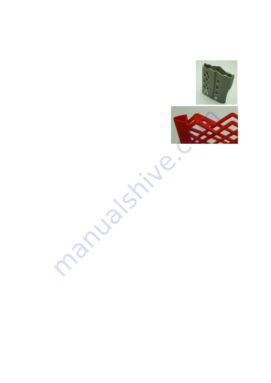
1. Solid parts (fuse and accessories - all grey parts). Use dense (100%)

infill. This is common way of printing objects and these parts should
be printable on every printer.

2. Shell parts (wings - all red parts). Use 0% infill and no

horizontal surfaces (thickness of the shell is one layer).
Only this way you can achieve required weight of the
plane.

You can check what method to use on what part in bill of materials table.

Nozzle size:         0.4 mm
Layer thickness:  0.19 mm
Rafts:                   yes

You can use any material you like, only limitation is high temperature from ironing when covering 
assembled parts. Heat from the iron can deform the parts. Although I was not able to damage any 
part and I tried to cover many materials (ABS, PLA ...), please test film covering on your testing 
part.

One of the goals when designing KRAGA models was to use minimal or no support during printing.
Removing support after printing is big pain and you can easily destroy your part. That is the reason 
why you should use default orientation of all parts during printing. 

I strongly recommend to mark every printed part with it's name (I'm using masking tape for that). 
There are many parts in this plane and from each part there is also mirror side which can easily 
cause confusion during assembly.

I also recommend to print parts in bulks, especially smaller parts like ailerons or horns. Otherwise 
there is not enough time for material cooling in each layer and you might end up with rough layers, 
ugly edges or print fail.

[email protected]

Summary of Contents for Maripi

Page 1: ...not share files that you bought Development of a new plane and support of the old ones is very time consuming Only with your help I can focus fully on this project and spend some quality time with my...

Page 2: ...1 37 wing_R_3 SHELL 1 38 wing_R_4 SHELL 1 39 wing_R_5 SHELL 1 40 back_wing_spar_2x1_245 2 41 main_wing_spar_6x4_454 4 42 servo_mount_wing_L_B SOLID 1 43 servo_mount_wing_L_F SOLID 1 44 servo_mount_win...

Page 3: ...arts Although I was not able to damage any part and I tried to cover many materials ABS PLA please test film covering on your testing part One of the goals when designing KRAGA models was to use minim...

Page 4: ...ts were added This fix was still not good enough That is why I improved it much more in this version I added more fillets on all critical places Air inlets are much smaller and moved away from motor m...

Page 5: ...on tube 6x4 mm 1m 2 carbon rod 3 mm 1 m 1 carbon rod 4 mm 1 m 1 covering film 2 m 1 wheels 45 mm or 50 mm max thickness 16 mm 2 pinned hinge 16x28x1 2 mm or Du Bro 117 11 propeller 10 inch 1 spinner 4...

Page 6: ...62 mm 2 fuse servo plate spar front 2x1 mm 68 mm 1 fuse servo plate spar back 2x1 mm 51 mm 1 wing joiner rod front 4 mm 300 mm 1 wing joiner rod back 4 mm 280 mm 1 landing leg spar front 3 mm 145 mm 2...

Page 7: ...ometimes the fit is too tight or you cannot insert joiners rods into wing spars at all You can use drill and wet sandpaper to make joiner rods thinner Use breathing mask to avoid inhaling carbon dust...

Page 8: ...spars through Both main wing spars main_wing_spar_6x4_454 should be aligned flush with base of wing_L_0 part Back wing spar back_wing_spar_2x1_245 should protrude 0 5 cm It s purpose is to fix back s...

Page 9: ...horten all hinges as shown on the picture It has no benefit in terms of added stiffness of rigidity to use whole hinge arm length as only small hinge area is in contact with the wing Be careful when u...

Page 10: ...ing it through service opening when the fuselage is assembled is more difficult When all the parts are on their position put glue on contact points where carbon spars are touching printed parts Canopy...

Page 11: ...mbly the stabilizer as sketched above Carbon spars protrude 1 cm from base of ver_stab_f_0 When all the parts are on their position put glue on contact points where carbon spars are touching printed p...

Page 12: ...moving part of the stabilizer as sketched above Carbon spar should be centered in the middle When all the parts are on their position put glue on contact points where carbon spars are touching printe...

Page 13: ...mbly first shorten all hinges and then insert the hinges into hinge slots and apply the glue from inner side of the main part Then insert all hinges into hinge slots on moving part and put the glue fr...

Page 14: ...on and it has to be done to make motor mount as strong as possible When spars are on their position apply more glue from inner side of fuse_0 There are spaces along spar leading tubes where you can pu...

Page 15: ...ordinary bicycle steel spoke 2mm thick Cut the head and the thread off make some kind of sharp edge and mount it into a drill This way you can drill through all spar leading holes to remove all print...

Page 16: ...rrow and have too much space in shoe It is enough to secure wheel_shaft_23 to the shoe only from one outer side with the glue First attach landing leg spars to the shoe_L part and only then attach the...

Page 17: ...s to cover wings after they are fully assembled center wing tip wing and aileron are glued together It is a little bit more demanding but it is definitely worth it Otherwise you are risking that when...

Page 18: ...g figure ESC If you opted for above mentioned motor option you need 40A speed controller for brushless motors ideally with SBEC for example this one HobbyKing 40A BlueSeries Brushless Speed Controller...

Page 19: ...ove All the linkages except for the rudder use 2x1mm carbon tube glued into threaded couplers and screwed into metal clevises Settings and flying Throws Use maximal possible throws on ailerons and rud...

Page 20: ...absorb the energy during landing or crash when the wings can detach easily To attach wing to the fuselage insert joiner rods into wing spars Use small rubber band to secure the wing in place by attac...

Reviews: