17 General Purpose Inputs/outputs
Kontron User's Guide EPIC/CE
49
17
General Purpose Inputs/outputs
The EPIC/CE Board comes with 26 General Purpose Input/Outputs (GPIOs). Each pin is individually
configurable as an input or open-drain output. When configured as output the user must provide a pull-
up resistor to the desired output voltage level. All output pins have 12mA drive strength. (See the
connector table in Appendix E for detailed information on each pin). The output low level is max. 0,4V.
17.1
Connector
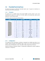
The GPIOs are available on the 2mm grid 2 row connector X3 (28 pins). To find the location of the
Connector on the EPIC/CE board, please see the Appendix E: Connector Layout chapter.
The following table shows the pin-out of the connector.
GPIO
Pin
Connector
Top View
Pin
GPIO
GP0
*(12csu)
1
2
GP14
*(12t)
GP1
*(12csu)
3
4
GP15
*(12t)
GP2
*(12cs)
5
6
GP16
*(12t)
GP3
*(12cs)
7
8
GP17
*(12t)
GP4
*(12cs)
9
10
GP18
*(24t)
GP5
*(12cs)
11
12
GP19
*(12t)
GP6
*(12cs)
13
14
GP20
*(12t)
GP7
*(12csu)
15
16
GP21
*(24t)
GP8
*(24t)
17
18
GP22
*(12csu)
GP9
*(12t)
19
20
GP23
*(12cs)
GP10
*(12t)
21
22
GP24
*(12cs)
GP11
*(12t)
23
24
GP25
*(12cs)
GP12
*(12t)
25
26
GND
GP13
*(12t)
27
28
GND
Notes:
*(12cs)
CMOS level Schmitt-trigger bi-directional pin and open-drain output with 12mA sink
capability
*(12csu)
CMOS level Schmitt-trigger bi-directional pin with internalpull up resistor and open-drain
output with 12mA sink capability
*(12t)
TTL level bi-directional pin and open-drain output with 12mA sink capability
*(24t)
TTL level bi-directional pin and open-drain output with 24mA sink capability
All of these signals are not galvanically isolated from the board. To ensure that the EPIC/CE Board is
protected from electrical damage, implement external protection circuitry such as optocouplers at
each signal.
Summary of Contents for EPIC/CE
Page 1: ...Kontron User s Guide EPIC CE Document Revision 1 14...
Page 2: ...This page intentionally left blank...
Page 88: ...25 Appendix C Block Diagram Kontron User s Guide EPIC CE 88 25 Appendix C Block Diagram...
Page 93: ...27 Appendix E Connector Layout Kontron User s Guide EPIC CE 93 27 2 Bottom Side...


