17 General Purpose Inputs/outputs
Kontron User's Guide EPIC/CE
50
17.2
Programming
17.2.1
16-Bit Operating Systems
The 26 GPIOs are driven by the two onboard Winbond W83627HF Super-I/O controllers on the Low Pin
Count (LPC) bus. The second controller serves the GPIOs 0 to 21 via ports 4E/4Fhex; the first controller
takes care of GPIOs 22 to 25 at ports 2E/2Fhex.
The W83627HF Super I/O controller consists of several logical devices, which correspond to individual
functionality. Each Logical Device has its own configuration registers. The designer can access the
desired configuration registers by selecting a logical device through the Extended Functions Data
Register (I/O port index register 4Eh and data register 4Fh, or 2Eh and 2Fh respectively). The following
table shows the relationship between Super I/O and GPIOs.
GPIO
Controller
Logical Device
Index Register Address Data Register Address
GP0-7
Super-I/O 2
Logical Device 7
4Eh
4Fh
GP8-13
Super-I/O 2
Logical Device 9
4Eh
4Fh
GP14-21
Super-I/O 2
Logical Device 8
4Eh
4Fh
GP22-25
Super-I/O 1
Logical Device 7
2Eh
2Fh
The programming of the GPIOs is done in 4 steps:
Switch the Super-I/O to Extended Configuration access.
Select the logical device to be accessed.
Reprogram the configuration register of the logical device.
Disable the Extended Configuration access.
Switching to Extended Configuration Access
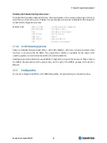
To enable the Extended Configuration Access, the Index Register of the corresponding Super-I/O has to
be written two times with a value of 87hex. The example below shows how to enable the first Super-I/O
for Extended Configuration accesses.
Example
code:
MOV DX,2EH
;Index Register Address
MOV
AL,87H
;Enable
Code
CLI
;Disable
Interrupts
OUT
DX,AL
;First
Write
JMP
$+2
;Wait
OUT
DX,AL
;Second
Write
STI
;Enable
Interrupts
Summary of Contents for EPIC/CE
Page 1: ...Kontron User s Guide EPIC CE Document Revision 1 14...
Page 2: ...This page intentionally left blank...
Page 88: ...25 Appendix C Block Diagram Kontron User s Guide EPIC CE 88 25 Appendix C Block Diagram...
Page 93: ...27 Appendix E Connector Layout Kontron User s Guide EPIC CE 93 27 2 Bottom Side...


