19 Power Interface
Kontron User's Guide EPIC/CE
55
19.1.2
+5V-only Power Supply on ATX connector
If you intend to use a +5V-only power supply on the board equipped with the ATX connector, connect the
+5V of the power supply to Pins 6, 7 and 8 (+5V and +5V_SB) and the Ground of the power supply to Pins
2, 3 and 10 (GND) of Connector X7. Leave all other pins (PS_ON included) unconnected. Peripherals
requiring other voltages need to be supplied separately.
19.1.3
AT Connector Version
This power interface is an option to the ATX power interface and uses Connector X8 (4 pins). For the
location of this connector see Appendix E: Connector Layout.
The EPIC/CE re5V-only. The +3.3V for onboard low-power devices is generated onboard by a
DC/DC converter. Peripherals req3.3V or other voltages need to be supplied separately. Any
+3.3V PC/104-Plus add-on card will be affected this way.
Upon request, it is possible to modify the EPIC/CE so that the module can supply the +3.3V for PC/104-
Plus devices via the onboard DC/DC converter. However, this modification has a limitation in which add-
on PC/104-Plus cards cannot exceed a supply current of 1A (1.5A absolute maximum).
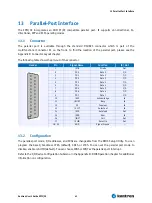
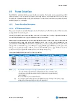
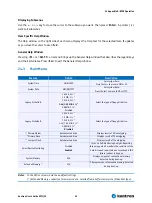
The following table shows the pin-out of the AT connector.
Header
Pin
Signal Description
Function
1
V5S *
+5V
2
GND
Ground
3
GND
Ground
4
VCC12 *
+12V
Notes
: (*)
To protect the external power lines of peripheral devices, make sure that:
-- the wires have the right diameter to withstand the maximum available current
-- the enclosure of the peripheral device fulfils the fire-protecting requirements of
-- IEC/EN 60950.
The current of the pins on this connector is limited to 13A/pin.
Warning: EPIC-CE in 5V-only version supply the +3.3V to the PC/104-Plus connector via an onboard DC/DC
converter. The DC/DC converter is only capable to supply a maximum of 500mA to +3.3V extension
cards. As there is no protection on this +3.3V supply, the user has to make sure not to exceed this value
with his PC/104-Plus add-on cards.
19.1.4
Configuration
The EPIC/CE comes with a power-management system that supports APM 1.2 and ACPI 2.0 features. You
can configure lots of options for power-saving states such as standby state with partial power reduction
and suspend state with full-power reduction. Please refer to the Power menu section in the Appendix B:
BIOS Operation chapter for more information on saving power.
Summary of Contents for EPIC/CE
Page 1: ...Kontron User s Guide EPIC CE Document Revision 1 14...
Page 2: ...This page intentionally left blank...
Page 88: ...25 Appendix C Block Diagram Kontron User s Guide EPIC CE 88 25 Appendix C Block Diagram...
Page 93: ...27 Appendix E Connector Layout Kontron User s Guide EPIC CE 93 27 2 Bottom Side...

