19 Power Interface
Kontron User's Guide EPIC/CE
56
19.2
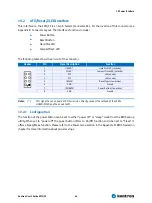
ATX/Reset/2LED Interface
This interface on the EPIC/CE is an 8-pin female (Connector X6). For the location of this connector see
Appendix E: Connector Layout. The interface’s functions include:
®
Power Button
®
Reset Button
®
Hard Disk LED
®
CompactFlash LED
The following table shows the pin-out of the connector.
Header
Pin
Signal Description
Function
1
HDLED *
Hard Disk LED (cathode)
2
CFLED *
CompactFlash LED (cathode)
3
VCC
+5V (anode)
4
VCC
+5V (anode)
5
/RESIN
Reset Input (low active)
6
GND
Ground
7
/PWRBTN
Power Button (low active)
8
GND
Ground
Notes
: (*)
This signal has an onboard 470 Ohm resistor. Directly connect the cathode of the LED to
HDLED/CFLED and the anode to VCC.
19.2.1
Configuration
The function of the power button can be set to either “power off” or “sleep” mode from the BIOS set-up
utility. When set to “power off” the power button offers an On/Off function and when set to “Sleep” it
offers a Sleep/Wake function. Please refer to the Power menu section in the Appendix B: BIOS Operation
chapter for more information about power savings.
Summary of Contents for EPIC/CE
Page 1: ...Kontron User s Guide EPIC CE Document Revision 1 14...
Page 2: ...This page intentionally left blank...
Page 88: ...25 Appendix C Block Diagram Kontron User s Guide EPIC CE 88 25 Appendix C Block Diagram...
Page 93: ...27 Appendix E Connector Layout Kontron User s Guide EPIC CE 93 27 2 Bottom Side...


