COMe-bSL6 – User Guide Rev. 1.4
www.kontron.com
// 11
6.4.1. Startup Scripting ................................................................................................................................................................................... 93
6.4.2. Create a Startup Script ....................................................................................................................................................................... 93
6.4.3. Examples of Startup Scripts ............................................................................................................................................................ 93
6.5. Firmware Update ..................................................................................................................................................................................... 94
List of Tables
Table 1: Pin Assignment of Type 6 and COMe-bSL6 ............................................................................................................................. 14
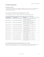
Table 2: Product Number for Commercial Temperature Grade Modules (0°C to +60°C operating) ..................................... 15
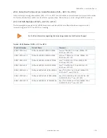
Table 3: R E2S Modules (R E2S, -40°C to +85°C) .................................................................................................................................... 16
Table 4: Product Specific Accessories ....................................................................................................................................................... 17
Table 5: COMe Type 6 Specific Accessories ............................................................................................................................................. 17
Table 6: General Accessories........................................................................................................................................................................ 17
Table 7: Memory Modules ............................................................................................................................................................................. 18
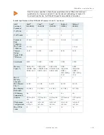
Table 8: Specifications of the COMe-bSL6 Processor Variants ........................................................................................................ 21
Table 9: General Purpose PCI-Express lanes ......................................................................................................................................... 25
Table 10: PCI-Express Graphics x16 (PEG) Port Bifurcation and Lane Mapping ......................................................................... 26
Table 11: PCI-Express Graphics x16 (PEG) Port Bifurcation and Lane Reversal Mapping ........................................................ 26
Table 12: COMe USB 3.0 Ports and USB 2.0 Ports ................................................................................................................................. 27
Table 13: COMe Connector PCH High Speed I/O Port Interfaces ...................................................................................................... 29
Table 14: ATX Mode Settings ....................................................................................................................................................................... 33
Table 15: Single Supply Mode Settings ..................................................................................................................................................... 33
Table 16: Heatspreader Test Temperature Specifications ................................................................................................................ 34
Table 17: 3-Pin Fan Connector Pin Assignment: .................................................................................................................................... 35
Table 18: Electrical Characteristics of the Fan Connector ................................................................................................................. 35
Table 19: Temperature Grade Specifications ......................................................................................................................................... 36
Table 20: Humidity Specifications ............................................................................................................................................................. 36
Table 21: Standards and Certifications ..................................................................................................................................................... 37
Table 22: MTBF Temperature de-Rating ................................................................................................................................................. 38
Table 23: Supported BIOS Features ........................................................................................................................................................... 40
Table 24: SPI Boot Pin Configuration ........................................................................................................................................................ 40
Table 25: Supported SPI Boot Flash Types for 8-SOIC Package ....................................................................................................... 41
Table 26: Reserved SM-Bus Addresses for Smart Battery Solutions on the Carrier ............................................................... 42
Table 27: Triple Stage Watchdog Timer- Time-out Events ............................................................................................................... 43
Table 28: General Signal Description ......................................................................................................................................................... 51
Table 29: Connector X1A Row A Pinout List ............................................................................................................................................ 52
Table 30: Connector X1A Row B Pinout List ............................................................................................................................................ 55
Table 31: Connector X1B Row C Pinout List ............................................................................................................................................. 58
Table 32: Connector X1B Row D Pinout List ............................................................................................................................................. 61
Table 33: Navigation Hot Keys Available in the Legend Bar .............................................................................................................. 64
Table 34: Main Setup Menu Sub-screens and Functions .................................................................................................................. 66
Table 35: Advanced Setup menu Sub-screens and Functions ......................................................................................................... 67
Table 36: Chipset Set > System Agent Configuration Sub-screens and Functions ................................................................... 78
Table 37: Chipset Set > PCH-IO Configuration Sub-screens and Functions ................................................................................ 82
Table 38: Security Setup Menu Functions ............................................................................................................................................... 88
Table 39: Boot Setup Menu Functions ...................................................................................................................................................... 89
Table 40: Save and Exit Setup Menu Functions .................................................................................................................................... 90
Table 41: List of Acronyms
........................................................................................................................................................................... 95
List of Figures
Figure 1: Block Diagram COMe-bSL6 .......................................................................................................................................................... 19
Figure 2: Module Dimensions ...................................................................................................................................................................... 39
Figure 3: Module Height ................................................................................................................................................................................ 39
Figure 4: X1A and X1B COMe Interface Connectors .............................................................................................................................. 50


