background image

10

1�1  Alert Symbol Marks

Safety alert symbols alert the user to matters and/or operations potentially hazardous to the user and 
other people. 
Read these messages and follow instructions carefully.
Be sure to read all instructions and safety standards and become thoroughly familiar with the product 
before starting operation.

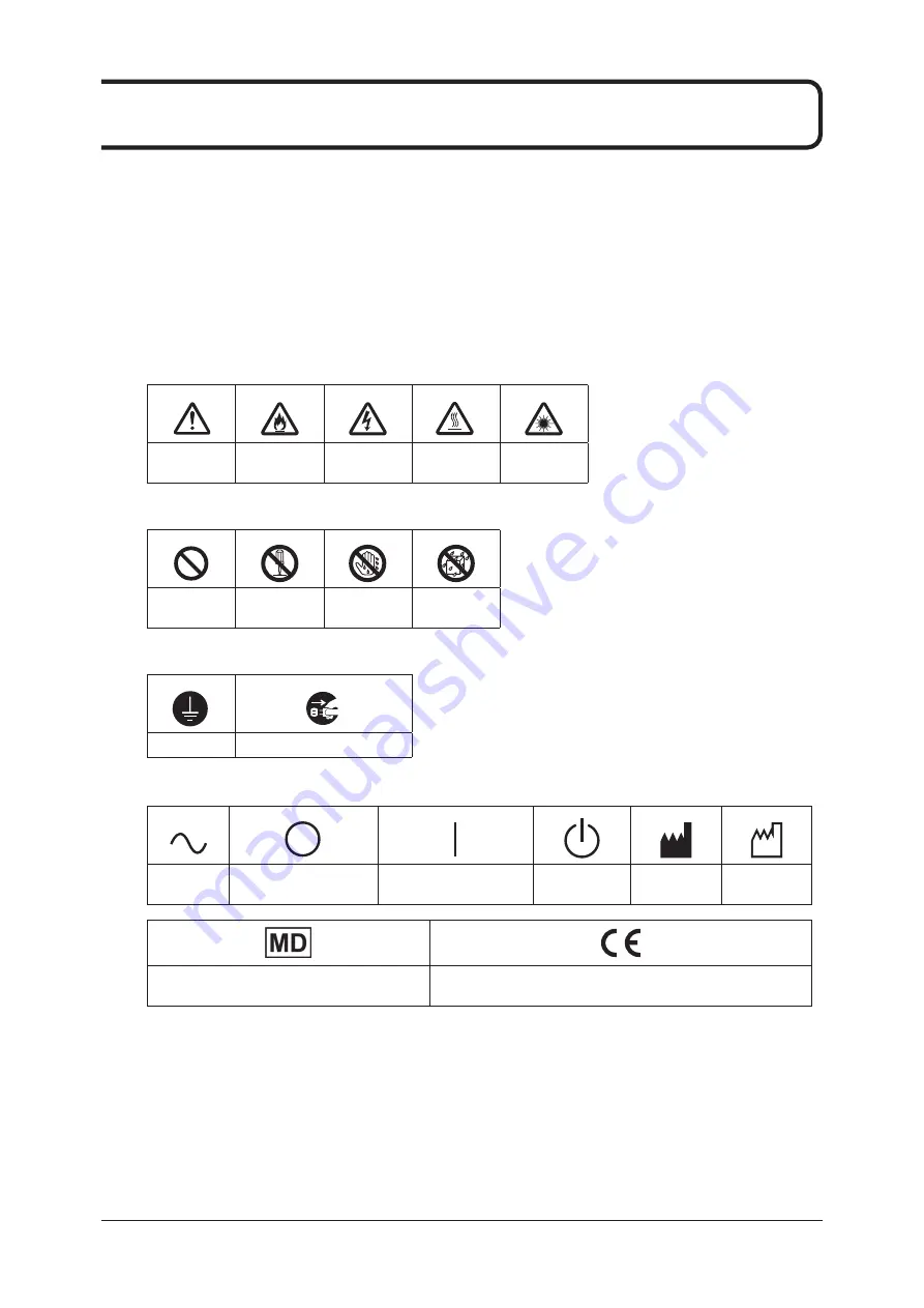
Description of Graphic Symbols

• 

Symbols indicating that care (including danger and warnings) should be taken

General  

Precautions

Danger of Fire

Danger of  

Electrical Shocks

High Temperature 

Warning

Danger of  

Laser

•  Symbols indicating prohibited acts

Prohibited

Do not  

disassemble

Do not touch with 

a wet hand

Do not expose to 

moisture

•  Symbols indicating compulsory or required acts

Ground

Remove plug from outlet

•  Other symbols

AC Voltage  

(Power Supply)

Power Supply Circuit Breaker 

OFF

Power Supply Circuit Breaker 

ON

Operation Switch

Manufacturer

Production Date

Indicates that this device is a medical device.

This symbol indicates that this device is in conformity with the 

Regulation (EU) 2017/745.

* If the contents of this page become illegible, please purchase a new manual (a fee is required.)

Summary of Contents for DRYPRO 873

Page 1: ...EN 13...

Page 2: ......

Page 3: ...r Right Side and Top 28 2 2 3 Operation Panel 29 2 2 4 Interior 30 2 2 5 Supply Tray 32 2 2 6 Expansion tray optional 32 2 2 7 Mammography media expansion tray optional 33 2 2 8 Sorter optional 33 2 3...

Page 4: ...m Supply tray 3 optional Elevating Transportation Unit 93 4 5 5 Film Jam from Supply tray 3 optional Position Regulation Unit 95 4 6 How to Handle Film Flaws 99 Chapter 5 Chapter 5 Maintenance 101 5 1...

Page 5: ...ntact Konica Minolta technical representatives Classifications This product is classified as below Classification based on the kind of protection for electric shock A power supply device for commercia...

Page 6: ...ed by installation relocation modification maintenance and repair made by anyone except Konica Minolta and contractors designated by Konica Minolta 4 Konica Minolta Inc is not responsible for any clai...

Page 7: ...P in our facility used for connection with this service Your equipment to be connected to the same network as that of this service 13 When this device is used various user and patient data stored with...

Page 8: ...r Konica Minolta service representative and the EU competent authorities Trademark Windows is a registered trademark of Microsoft Corporation in the United States and or other countries Company names...

Page 9: ...9 Chapter 1 Safety Warnings Precautions...

Page 10: ...er of Fire Danger of Electrical Shocks High Temperature Warning Danger of Laser Symbols indicating prohibited acts Prohibited Do not disassemble Do not touch with a wet hand Do not expose to moisture...

Page 11: ...njuries if not avoided WARNING Indicates dangers that may result in death or serious injuries if not avoided CAUTION Indicates dangers that may result in medium level wounds or minor injuries if not a...

Page 12: ...DRYPRO 873 shown below This is to remind our customers of the possible dangers that can occur when using the machine 1 3 1 Information on Warning Labels Laser warning label Laser Power Label Class 1...

Page 13: ...1 2 3 4 5 6 7 8 9 1 0 1 1 1 2 13 Warning Labels Load film label Film package opening warning label 1 3 2 Locations of Warning Labels Internal View Change deodorant filter Clear jam label...

Page 14: ...Warning Labels Rear and Right Side View Laser Power Label Class 1 Laser Product label Laser warning label Supply Tray Load film label Film package opening warning label Improper loading prevention lab...

Page 15: ...cifications If you use power supply that does not meet specifications or that does not supply sufficient cur rent it could cause overheating of electrical components or fire 1 4 2 Precautions for Relo...

Page 16: ...nd unplug the power cord It could cause failure depending on the severity of lightening This product is intended for use for printing image data Do not use for other purposes Failure to observe this c...

Page 17: ...errors in operation or images Contact Konica Minolta technical representatives In order to obtain high quality images be sure to perform regular maintenance operations Failing to do so causes dirt an...

Page 18: ...ispose of this product together with your household waste Please refer to the information of your local community or con tact our dealers regarding the proper handling of end of life electric and elec...

Page 19: ...rcuit different from that to which the other device s are connected Consult the manufacturer or field service technician for help WARNING Do not use mobile RF communication devices such as mobile phon...

Page 20: ...discharge ESD IEC 61000 4 2 6kV contact 6kV contact Floors should be wood concrete or ce ramic tile If floors are covered with syn thetic material the relative humidity should be at least 30 Main powe...

Page 21: ...eters m Field strengths from fixed RF transmitters as de termined by an electromagnetic site survey a should be less than the compliance level in each frequency range b Interference may occur in the v...

Page 22: ...tput power of transmitter W Separation distance according to frequency of transmitter m 150 kHz to 80 MHz d 1 2 P 80 MHz to 800 MHz d 1 2 P 800 MHz to 2 5 GHz d 2 3 P 0 01 0 12 0 12 0 23 0 1 0 38 0 38...

Page 23: ...rt 100 kHz repetition frequency Surges IEC 61000 4 5 0 5 kV 1 kV line to line 0 5 kV 1 kV 2 kV line to ground Conducted desturbances in duced by RF fields IEC 61000 4 6 3 V 0 15 MHz 80 MHz 6V in ISM b...

Page 24: ...est frequency MHz Modulation Immunity test level V m 385 Pulse modulation 18 Hz 27 450 FM 5 kHz deviation 1 kHz sine 28 710 Pulse modulation 217 Hz 9 745 780 810 Pulse modulation 18 Hz 28 870 930 1720...

Page 25: ...25 Chapter 2 Product Outline...

Page 26: ...73 2 1 1 System Configuration Example Images to print to film are sent to the DRYPRO 873 from diagnostic equipment with a DICOM com munication function DRYPRO 873 console CT MRI Up to 16 units Example...

Page 27: ...r or all trays are empty Red light ON Not ready to print one tray is empty maintenance is being performed film is being replaced filter is being replaced or unit is being cleaned 2 Operation switch St...

Page 28: ...Function Refer to 1 Air intake Draws air to cool the inside 5 3 3 Cleaning Air Intakes Outlets page 108 2 LAN cover Ethernet port and UPS serial port cover 2 2 4 Interior page 30 3 Top right cover Ope...

Page 29: ...ations 3 4 Calibration page 50 3 6 Maintenance Mode page 54 4 4 1 Reset from Operation Panel page 82 5 2 2 How to Print QC Patterns page 104 5 Test print button Press this button to print QC patterns...

Page 30: ...ve a film stuck in the heat process unit when a jam occurs 4 5 2 Film Jam in Heat Process Unit page 88 2 Deodorant filter Removes odors emitted during heat process Periodic change is needed 5 4 Changi...

Page 31: ...l the inside 5 3 3 Cleaning Air Intakes Outlets page 108 3 Ethernet port Used for network connection 4 UPS serial port When a backup battery is used its serial cable is con nected here Ethernet Port L...

Page 32: ...ilm regulation pin fixed Regulates the film position 2 Film regulation pin mounting hole When using 14 x 14 in and 11 x 14 in films install the supplied film regulation pins 3 Intermediate plate Resin...

Page 33: ...ber Name Function Refer to 1 Mammography media expansion tray Lispl 873M This is the mammography media expansion tray Attach it to supply tray 3 2 2 8 Sorter optional 1 LiS 873 Num ber Name Function R...

Page 34: ...nd transports it to the position regulation unit 2 2 6 Expansion tray optional page 32 2 2 7 Mammography media expan sion tray optional page 33 4 Elevating trans portation unit Transport film transpor...

Page 35: ...35 Chapter 3 Operation from Main Unit...

Page 36: ...873 Leave the power supply circuit breaker on during normal use Operation Switch Power supply circuit breaker 3 1 1 How to Start 1 Turn on the DRYPRO 873 power supply circuit breaker If the power sup...

Page 37: ...up The main unit can be used in standby mode by configuring PC For information on configuring PC contact Konica Minolta technical representatives The main unit can be started from standby mode by usi...

Page 38: ...age Printing does not appear in the display window If the machine is not shut down after the expiration of three min utes or more following a shutdown operation press and hold the operation switch aga...

Page 39: ...second The message Now shutting down Please wait a while appears in the display win dow and the status LED turns off The machine will be shut down in about 10 seconds Leave the power supply circuit b...

Page 40: ...e displayed alter nately Roller Cleaning must be performed Filter exchange Open the front cover The above messages are displayed alter nately The filter must be replaced Perform Prev maintenance Pleas...

Page 41: ...mation for tray 2 is displayed to the right of the icon When the tray becomes empty the icon is inverted for a set period of time tray 3 Information for tray 3 is displayed to the right of the icon Wh...

Page 42: ...mode function Sleep mode is a power saving mode that enables automatic startup when the main unit has not been operated either from the operation panel or by printing for a specified period of time 1...

Page 43: ...anged from PC The main unit cannot be operated while the following message appears 3 2 6 PC Connection Status The connection status with PC is displayed If the connection status appears as shown below...

Page 44: ...nformation display area In this case loading supply films following the steps below 1 Press the tray button The following message appears in the display window The supply tray pops out by several cent...

Page 45: ...rawn forth Failure to observe this caution may cause fault 4 When the cursor indicators light up use the Test print and Calibration buttons to display the next step to be taken in the display window 5...

Page 46: ...taken in the display window 7 Remove the seals to extend the front and rear ends of the package bar rier bag 8 When the cursor indicators light up use the Test print and Calibration buttons to display...

Page 47: ...ht to left or left to right direction After using the special cutter store it in the cutter pocket of the main unit After cutting it off do not open the mouth of the package barrier bag Otherwise the...

Page 48: ...rrier bag protruded from the supply tray When pushing the supply tray unit in do not stop until the opera tion is completed and make sure you push the unit firmly to the back of the main unit 13 When...

Page 49: ...heet of film printed with the calibration pattern for automatic density correction is output when the first print job is received after film has been loaded and when warm up is completed due to the se...

Page 50: ...tion i e data whose density is not corrected If you check or manage the density use the the QC pattern output in test print 3 5 Test Print page 52 5 2 Operation of Test Print page 103 1 When Ready app...

Page 51: ...sitometer Once calibration has been completed the message display window goes back to the nor mal display Ready If the calibration pattern cannot be read properly with the built in densitometer the me...

Page 52: ...print QC patterns from the operation panel of the main unit For information about the operation of test print in general see 5 2 Operation of Test Print page 103 and how to judge the results after pr...

Page 53: ...Print The QC patterns as shown below will be printed The message display window goes back to the normal display Ready If the film type of the selected tray is M Mammo the calibration pattern and Mamm...

Page 54: ...ic equipment All stored print jobs are executed after exiting maintenance mode Maintenance mode is not available when a user is logged in from an external device such as PC 3 6 1 Enabling and Using Ma...

Page 55: ...message is displayed indicating this 8 Wait a moment or press any button to return to page one of the mainte nance menu With the maintenance menu displayed use the Test print and Calibration buttons...

Page 56: ...since the last roller cleaning Password Displays the screen in which a password is entered System Reset Clears all queued jobs and restarts the main unit Main Unit Settings Lets you configure the tray...

Page 57: ...film output normally and does not include calibration sheets output after film is loaded Cumulative data Meaning Daily When Daily is selected the daily cumulative data for an 90 day period is display...

Page 58: ...the order of Tray 1 Tray 2 Tray 3 Tray 1 The available settings vary depending on the size and type of the loaded film 5 Select OK and press the Service Enter button to display the cumula tive data f...

Page 59: ...the previous screen Results Data Screen This displays the results for the three most recent QC patterns The density values x100 for steps 1 to 4 are displayed If there is a density read error for ste...

Page 60: ...ion buttons to move the cursor to YES or NO Press the Service Enter button to select the item Select YES to delete the the QC results for the selected tray Select NO to return to the previous screen P...

Page 61: ...aning icon appears in the display window each time 2 000 sheets has been printed Selecting and activating this item enables cleaning of the cleaning roller This function can also be used to clean the...

Page 62: ...isplay window and open the lower right cover 5 Follow the instructions on the label of the lower right cover for cleaning the cleaning roller Cleaning Method Lift the lever up and down to rotate the c...

Page 63: ...1 0 1 1 1 2 63 Maintenance Mode 2 Wipe the cleaning roller with the cloth 3 Lift the lever up and down once 4 Repeat Steps 1 to 3 10 times 5 Wipe the guide plate and roller with the cloth Close the l...

Page 64: ...d PC also restarts When system reset is performed all queued print data is deleted 1 Enable maintenance mode 3 6 1 Enabling and Using Maintenance Mode page 54 2 Use the Test print and Calibration butt...

Page 65: ...ilm Type Select the film type B BLUE C CLEAR M MAMMO Settings B Blue and C Clear are not available when a mammography media tray is installed in supply tray 3 Sorter Use Select whether to use the sort...

Page 66: ...Enter button to enable or disable the selected tray ON OFF ON Film Size Press the Service Enter button to change the film size of the selected tray 14x17 14x14 11x14 10x12 8x10 14x17 Film Type Press t...

Page 67: ...disconnect from the computer may appear in the display window This is not a malfunc tion The main unit quickly re establishes a connection 3 6 10 Current Date Time You can set the year month day hour...

Page 68: ...select the hour 01 02 11 12 01 MIN Press the Service Enter button to select the minutes 00 01 58 59 00 6 Move the cursor to OK and press the Service Enter button to save the settings If the date and...

Page 69: ...aintenance menu appears Select NO to return to the maintenance menu without saving the settings The date and time setting may not be available depending on the setting of PC The date can be set up to...

Page 70: ...its 0 1 8 9 0 Set this between 20 and 720 minutes You cannot set to less than 20 minutes or more than 720 minutes 6 Move the cursor to OK and press the Service Enter button to save the settings If the...

Page 71: ...following message appears in the display window 4 Use the Test print and Calibration buttons to move the cursor to an item and press the Service Enter button to select that item Press the Reset Cancel...

Page 72: ...d Using Maintenance Mode page 54 2 Use the Test print and Calibration buttons to move the cursor to the Ser vice Information icon Press the Service Enter button to select an item 3 The following messa...

Page 73: ...upply tray unit When you want to change the film size to 10x12 or 8x10 or from 10x12 or 8x10 to a different size the settings of some mechanical parts need to be changed Contact Konica Minolta technic...

Page 74: ...hment position of the film regulation pin Film regulation pin mounting hole 11x14 in Film regulation pin mounting hole 14x14 in Intermediate Plate Guide hole Film regulation pin mounting hole Size of...

Page 75: ...m regulation pin mounting hole Intermediate Plate Cross section Protrusion Note The type of Allen key included might differ from that shown in the illustration When changing from 14x14 inch or 11x14 i...

Page 76: ...76...

Page 77: ...77 Chapter 4 Troubleshooting...

Page 78: ...3 1 3 How to Shut Down page 38 Cannot open trays when loading a film Is the main unit printing something Is the another user logged in for maintenance 3 3 Loading Films page 44 An error message is di...

Page 79: ...g amount of film indicator continues to show 0 the tray icon continues to flash and the tray button remains lit Perform the procedure again from the step 1 of 3 3 Loading Films page 44 Closed the tray...

Page 80: ...upply tray 1 opens when film is not being loaded Close the supply tray 1 E4225 Error message Close the Tray Supply tray 2 opens when film is not being loaded Close the supply tray 2 E4325 Error messag...

Page 81: ...size or type is changed on the main unit opera tion panel A film size type input image that differs from the main unit settings was specified Check the film size type settings for the input destinatio...

Page 82: ...he message display window on the operation panel In addition the Reset Cancel lamp lights up and the red status lamp illuminates After handling the error according to the error message reset the error...

Page 83: ...t down in about 10 seconds 2 Check that the machine has been shut down and then press and hold the operation switch until a beep sounds approximately one second When Ready appears in the display windo...

Page 84: ...s to 1 minute Power LED 2 When the power LED turns off press the power switch again to start PC If an error occurs contact your Konica Minolta technical representatives If PC is not stored below the m...

Page 85: ...or code 4211 4410 4411 4412 4510 4522 or 4512 is displayed Error code 4211 is only displayed when supply tray 3 is not set When a film jam has occurred between the Supply tray 1 and 2 and the position...

Page 86: ...n of the arrow and open the top right cover Lever B Do not push down the open top right cover or place an object on it Failure to observe this caution may cause damage to the top right cover Do not sc...

Page 87: ...on or the Calibration button to display the next step to be taken in the display window 8 Close all covers Once the film jam has been cleared the machine will automatically return to the Ready state W...

Page 88: ...move the film following the steps below 1 A description of the step to be taken appears in the display window 2 Open the front cover Do not push down the open front cover or place an object on it Fail...

Page 89: ...n the display window 6 Remove the film from the film ejection port When the film is not ejected out of the ejection port after rotating lever A five to six times go to step 8 After completion of clear...

Page 90: ...ts at the top edge of the front cover are placed in the correct position on the main unit 4 5 3 Film Jam in the Sorter Unit optional Error code 4511 4610 4611 or 4712 is displayed Error codes 4511 461...

Page 91: ...longer comes out of the supply tray Lever A When the film is not ejected out of the ejection port after rotating lever A five to six times go to step 8 After completion of clearing the film jam if the...

Page 92: ...cursor indicators light up press the Test print button or the Calibration button to display the next step to be taken in the display window 8 Close all covers When closing the front cover and sorter c...

Page 93: ...it Error code 4311 is displayed 1 A description of the step to be taken appears in the display window 2 Open the lower right cover Do not push down the open lower right cover or place objects on it as...

Page 94: ...ion button to display the next step to be taken in the display window 4 Remove the film from the elevating transportation unit 5 When the cursor indicators light up press the Test print button or the...

Page 95: ...unit 4 5 5 Film Jam from Supply tray 3 optional Position Regulation Unit Error code 4211 is displayed Error codes 4211 only displayed when the supply tray 3 optional is me chanically installed 1 A de...

Page 96: ...irection of the arrow and open the top right cover Lever B Do not push down the open top right cov er or place objects on it as this may dam age the top right cover Be careful not to damage the inside...

Page 97: ...right cover or place objects on it as this may damage the lower right cover Be careful not to damage the inside of the lower right cover as this can damage the film 7 When the cursor indicators light...

Page 98: ...icators light up press the Test print button or the Calibration button to display the next step to be taken in the display window 10 Close all covers When closing the front cover top right cover and l...

Page 99: ...ay or mammography media expansion tray is at tached Wiping the feed guides too harshly may damage them which in turn would cause more film flaws Therefore wipe them carefully If film flaws affecting t...

Page 100: ...100...

Page 101: ...101 Chapter 5 Maintenance...

Page 102: ...Roller Every 2 000 prints mammography media users Maintenance and Items to be Checked by Service Personnel Other major maintenance and items to be checked are as follows These are included in the mai...

Page 103: ...alue When QC patterns are printed three times with a reference value not set in cases where this machine is used for the first time installation or a reference value is reset a reference value is auto...

Page 104: ...s of the available trays light up 2 Press the tray button of the tray for which to perform a test print Printing of the test print begins 3 The following message appears when printing of the test prin...

Page 105: ...etric pattern as shown is printed 2 Alphabetic numeric characters on the film image can be properly identified 3 No speckle noise was created on all or part of the film image 4 No horizontal stripe wa...

Page 106: ...he correct density value two to three digits is displayed Table 1 Item Number Item to Be Checked for Film Types B and C Item to Be Checked for Film Type M Step 1 density Within 0 05 of the initial val...

Page 107: ...n tray tends to be dusty Dust could damage the printed film Wipe off the dust with dry cloth once every three months 5 3 2 Cleaning Supply Tray Keep the inside of the supply tray clean Wipe off the du...

Page 108: ...st from outer side once every six months to prevent the air intakes and outlets from get ting clogged with dust Air intake Air intake Air intake Exhaust duct Air outlet 5 3 4 Cleaning the Cleaning Rol...

Page 109: ...e last filter replacement Change the deodorant filter following the steps below 1 Open the front cover Do not push down the open front cover or place an object on it Failure to observe this caution ma...

Page 110: ...r indicators light up use the Test print and Calibration buttons to display the next step to be taken in the display window 5 Pull out the deodorant filter case 6 When the cursor indicators light up u...

Page 111: ...dex finger and move it up and down In this way you can remove the filter without touching it 8 Have a new deodorant filter ready and install it in the case Make sure that the tab hitches to the filter...

Page 112: ...nt filter case in the main unit Push the deodorant filter case as far as it will go and then push it down ward 11 When the cursor indicators light up use the Test print and Calibration buttons to disp...

Page 113: ...12 Close the front cover When closing the front cover check that two magnets at the top edge of the front cover are placed in the correct position on the main unit Once the front cover has been close...

Page 114: ...Roller Cleaning icon appears in the display window after every 2 000 sheets printed Selecting and activating this item enables cleaning of the cleaning roller This function can also be used to clean...

Page 115: ...115 Appendix...

Page 116: ...size of 43 75 m For an image size of 43 75 m 14 17 inch size film 30 sec cycle equivalent to 120 pages per hour or faster 14 14 inch size film 27 sec cycle equivalent to 130 pages per hour or faster...

Page 117: ...15 16 20 24 25 30 35 36 42 48 54 56 60 63 64 Negative Positive Available Image Cropping Border Available Border Can be set to black white Stamp Recorded in one or two lines of the film can be output b...

Page 118: ...age anomalies Resolution check Check that thin line is resolved us ing a magnifying glass 9 Horizontal thin line upper 10 Vertical thin line lower Instead of checking with a magnify ing glass if the d...

Page 119: ...f the film image 7 No image wear was created on all or part of the film image 8 No image anomaly other than items in 3 to 7 occurred on all or part of the film image Resolution 9 The horizontal thin l...

Page 120: ...120...

Page 121: ...121...

Page 122: ...122...

Page 123: ......

Page 124: ...ia Private Ltd Office No 201 2nd Floor Atrium 2 Next to Courtyard Marriott Hotel Andheri Kurla Road Chakala Andheri East Mumbai 400093 India TEL 91 22 61916900 Konica Minolta Business Solutions Canada...

Reviews: