Operation
OPERATION
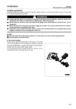
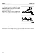
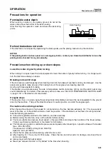
Adjusting work equipment posture
3-90
Adjusting work equipment posture
0.
WARNING
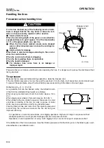
Stop the machine on flat ground and put blocks in
front and behind the wheels.
Set parking brake lever to the LOCK position.
Secure the front and rear frames with the safety bar.
Always attach the warning tag to the work equipment
control lever.
Do not go under the work equipment when the arm is
raised. To support the work equipment securely, use a
strong support that can withstand the weight of the
work equipment and prevent the arm coming from
down.
The boom kickout makes it possible to set the bucket so that it
automatically stops at the desired lifting height (lift arm higher
than horizontal) and the bucket positioner makes it possible to
set the bucket so that it automatically stops at the desired dig-
ging angle. The setting can be adjusted to match the working
conditions.
Adjusting boom kickout
0.
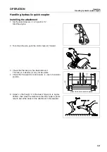
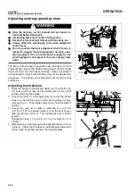
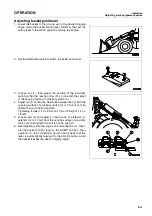
1. Raise the bucket to the desired height, set the lift arm con-
trol lever at HOLD, then set the safety lever to the LOCK
position and stop the engine.
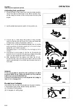
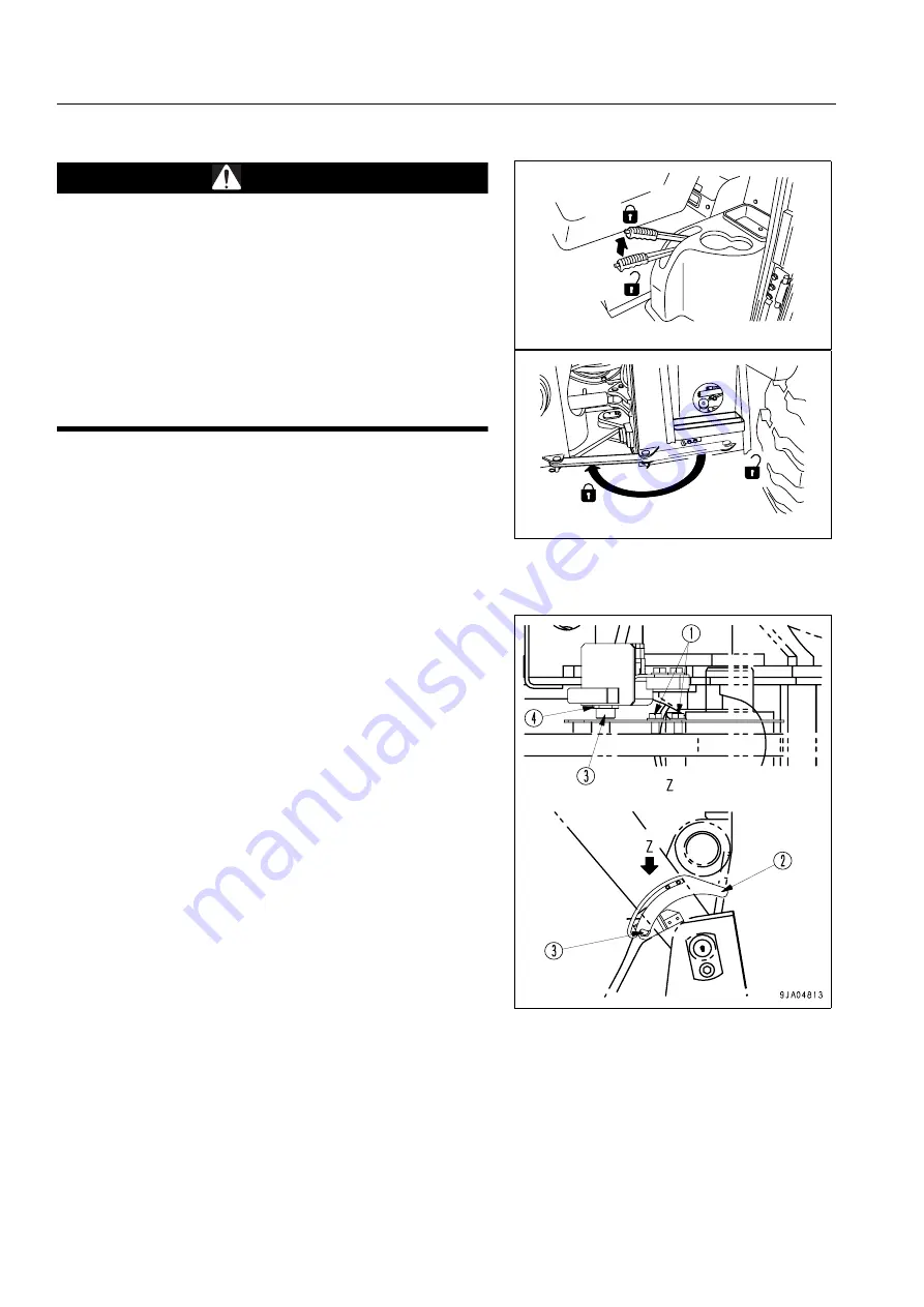
2. Loosen two bolts (1), and adjust plate (2) so that the bottom
edge is in line with the center of the sensing surface of prox-
imity switch (3). Then tighten the bolts to hold the plate in
position.
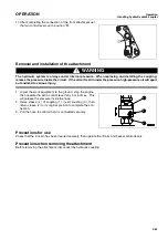
3. Loosen two nuts (4) to make a clearance of 3 to 5 mm
(0.118 to 0.197 in) between plate (2) and the sensing sur-
face of proximity switch (3). Then tighten the nuts to hold in
position.
Tightening torque: 17.2 ± 2.5 N·m (1.75 ± 0.25 kgf·m, 12.7 ±
1.8 lbft)
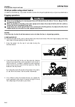
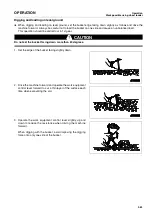
4. After adjusting, start the engine and operate the lift arm con-
trol lever. Check that the lever is automatically returned to
HOLD when the bucket reaches the desired height.
9EA04476-A
Free
Lock
9EA04781A
Free
Lock
Summary of Contents for WA250PT-5H
Page 2: ......
Page 3: ...FOREWORD 11...
Page 16: ...Contents FOREWORD 1 14...
Page 24: ...SAFETY 2 2...
Page 58: ...Precautions with tires SAFETY Precautions when storing tires 2 36...
Page 60: ...OPERATION 3 2...
Page 233: ...TECHNICAL DATA 45...
Page 235: ...TECHNICAL DATA Technical data 5 3...
Page 250: ...Central lubrication system ATTACHMENTS OPTIONS 6 14...
Page 251: ...INDEX 67...
Page 252: ...INDEX 7 2...
Page 255: ...Index 7 5...

