background image

GENERAL  PRECAUTIONS  COMMON  TO  OPERATION
AND MAINTENANCE

Mistakes  in  operation,  inspection,  or  maintenance  may  result  in  serious  personal  injury  or  death.  Before  per-
forming operation, inspection, or maintenance, always read “SAFETY”, Operation and Maintenance Manual of
standard machines and this manual carefully and obey the warnings.

PRECAUTIONS WHEN GETTING ON OR OFF MACHINE

PRECAUTIONS WHEN STANDING UP FROM OPERATOR'S SEAT

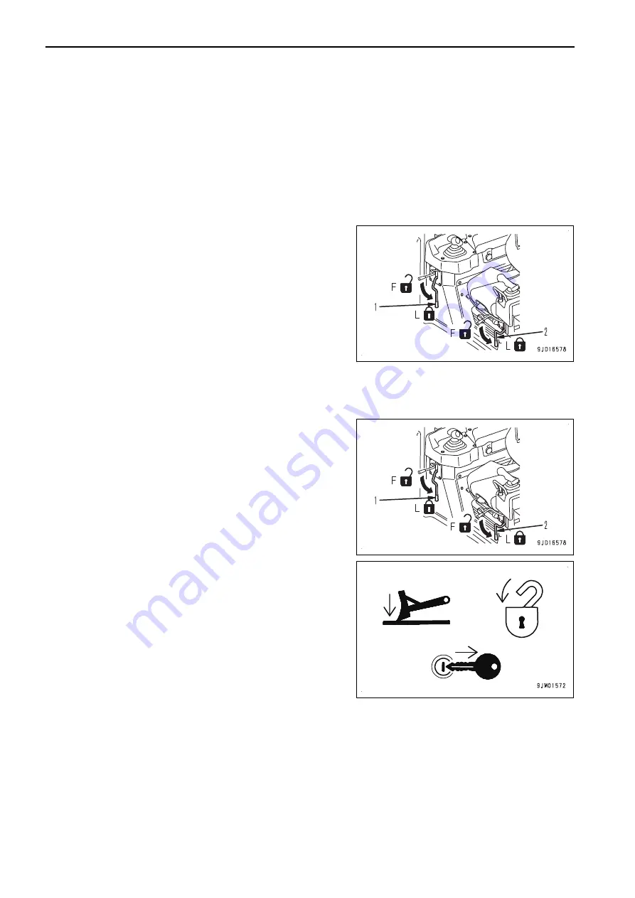
Before standing up from the operator's seat to adjust the seat,
always perform the following. Turn off the automatic control of
blade.  Lower  the  work  equipment  to  the  ground,  set  work
equipment lock lever (1) and parking brake lever (2) to LOCK
position (L), and stop the engine.
If  the  control  levers  are  touched  by  mistake,  there  is  danger
that  the  machine  may  suddenly  move  and  cause  serious  per-
sonal injury or death.

PRECAUTIONS WHEN LEAVING MACHINE

If the proper procedures are not taken when parking the machine, the machine may suddenly move off by itself,
and this may lead to serious personal injury or death. Always observe the following.
When leaving the machine, always turn the automatic control of
blade  OFF  and  lower  the  work  equipment  to  the  ground.  Set
work  equipment  lock  lever  (1)  and  parking  brake  lever  (2)  to
LOCK position (L), and stop the engine. In addition, lock all pla-
ces and always take the key with you and leave it in the speci-
fied location.

PRECAUTIONS FOR BLADE AUTOMATIC CONTROL

• While the automatic control of blade is in operation, the blade moves even if the operator does not operate

the blade control lever.
Before turning the automatic control of blade ON, check thoroughly that there are no persons or obstacles
in the area around the machine.

• While the automatic control of blade is in operation, if the operator operates blade control lever, this blade

lever operation is given the priority and the blade moves as operated by the operator. When the operator
stops lever operation, the automatic control of blade restarts.

GENERAL PRECAUTIONS COMMON TO OPERATION AND MAINTE-
NANCE

SAFETY

2-2

Summary of Contents for D51EXi-24

Page 1: ...us injury or death Operators and maintenance personnel must read this manual before operating or maintaining this machine This manual should be kept inside the cab for reference and periodically reviewed by all personnel who will come into contact with the machine Operation Maintenance Manual EENAM03570 WARNING ORIGINAL INSTRUCTIONS ...

Page 2: ......

Page 3: ...serv ice damage to the product or safety risks including personal injury or death Intelligent Machine Control is the system that utilizes ICT Information Communication Technology in each stage of earth moving operation such as survey design operation supervi sion examination and maintenance It enables the highly efficient and highly accurate earth moving operation by utilizing information provided...

Page 4: ...ays keep this Operation and Maintenance Manual in the indicated location so that all relevant personnel can read it at any time Storage location for the Operation and Maintenance Manual It is provided on the back of the backrest of operator s seat If this manual is lost or damaged contact Komatsu or your Komatsu distributor and tell them about the machine model name and the serial No immediately t...

Page 5: ... safety mes sage This signal word indicates an imminently hazardous situation which if not avoided will result in death or serious injury This signal word indicates a potentially hazardous situation which if not avoided could result in death or serious injury This signal word indicates a potentially hazardous situation which if not avoided may result in minor or moderate injury It may also be used...

Page 6: ...ion and display it on the control box screen By using this function the progress of opera tion can be checked in real time on the control box screen In order to use the blade automatic control or current ground display as built function following device is need ed besides this machine GNSS satellite GPS GLONASS Use it at a place under the open sky where has no obstacle Base station For the usable ...

Page 7: ...ARTING ENGINE 3 16 OPERATIONS AND CHECKS AFTER STARTING ENGINE 3 17 METHOD FOR STOPPING ENGINE 3 19 METHOD FOR USING AUTOMATIC BLADE CONTROL 3 21 TRANSPORTATION 3 60 REMOVE RADIO DEVICE ANTENNA CABLE 3 60 REMOVE AND INSTALL ANTENNA FOR NETWORK MODEM 3 60 PRECAUTIONS FOR LONG TERM STORAGE 3 64 TURN BATTERY DISCONNECT SWITCH TO OFF POSITION BEFORE LONG TERM STORAGE 3 64 TROUBLES AND ACTIONS 3 66 OTH...

Page 8: ...MC 4 82 MAIN WINDOW DISPLAY 4 84 ELEVATION CONTROL KEY 4 84 SLOPE CONTROL KEY 4 85 SHORTCUT ON THE MAIN WINDOW 4 86 TOOLBAR ON THE MAIN WINDOW 4 89 PAN OF MAIN MAP VIEW 4 91 OPERATION ON MAIN MENU 4 92 METHOD FOR DISPLAYING GNSS INFORMATION 4 92 METHOD FOR ADJUSTING CUT FILL OFFSETS 4 94 METHOD FOR CHANGING GRADE INDICATOR DISPLAY 4 94 METHOD FOR CHANGING DISPLAY OF LIGHT BAR 4 96 OPERATION USING ...

Page 9: ...hich are necessary to provide the efficient operation with intelligent Machine Control Please follow the instructions described in the Operation and Maintenance Manual for the standard machine for safety information of the whole ma chine 2 1 ...

Page 10: ...rking the machine the machine may suddenly move off by itself and this may lead to serious personal injury or death Always observe the following When leaving the machine always turn the automatic control of blade OFF and lower the work equipment to the ground Set work equipment lock lever 1 and parking brake lever 2 to LOCK position L and stop the engine In addition lock all pla ces and always tak...

Page 11: ...mediately if any When performing the inspection maintenance moving and loading unloading on the trailer etc i e other operation than the operation by intelligent Machine Control at the jobsite turn off the automatic control of blade then turn off the control box power supply SAFETY GENERAL PRECAUTIONS COMMON TO OPERATION AND MAINTE NANCE 2 3 ...

Page 12: ...n the automatic control of blade the response of the blade will be slow or the blade will move suddenly and this may lead to unexpected accidents so always perform the warming up operation Particularly in a cold weather be sure the warm up operation is completed If the battery electrolyte is frozen do not charge the battery or start the engine with a different power source There is a hazard that t...

Page 13: ... performing the check and adjustment for the automatic control of blade turn on the control box power supply and perform the check and adjustment Check that there are no persons or obstacles in the area around the machine PRECAUTIONS FOR GNSS ANTENNA Cable connector of the GNSS antenna is looseness free structure Check is not needed If the GNSS antenna contacts with obstacles during operation or t...

Page 14: ......

Page 15: ...hich are necessary to provide the efficient operation with intelligent Machine Control Please follow the instructions described in the Operation and Maintenance Manual for the standard machine for operation information of the whole ma chine 3 1 ...

Page 16: ...nder with stroke sensor 2 GNSS antenna 3 Radio antenna 4 Blade tilt cylinder with stroke sensor 5 Blade lift cylinder with stroke sensor MACHINE OUTSIDE EQUIPMENT NAME 1 GNSS satellite GPS 2 GNSS satellite GLONASS 3 Base station GENERAL VIEW OPERATION 3 2 ...

Page 17: ... Manual switch 3 ICT sensor controller inside the cover 4 GNSS receiver inside the cover 5 GNSS radio device 6 Cut Fill offsets switch Up 7 Cut Fill offsets switch Down 8 Back grade mode switch 9 Network modem if equipped OPERATION GENERAL VIEW 3 3 ...

Page 18: ...Sitelink3D messaging 11 Start Stop As built updates 12 Toggle As built mode 13 iB logo key 14 Zoom in key 15 Zoom out key 16 Toggle main view 17 Right window 18 Lower window 19 Slope control key 20 Back grade mode indicator 21 AUTO indicator The figure shows a typical example of the control box main window The contents displayed on the screen depends on the setting GENERAL VIEW OPERATION 3 4 ...

Page 19: ...ctly to operate it 1 Power ON switch green 2 Power OFF switch red 3 USB port Place the machine on a level ground under the open sky turn on the power of base station and then turn on the control box power supply to perform the inspection If the control box starts operation on the slope of which pitching angle inclination in front or rear or rolling angle inclination in right or left is 20 or more ...

Page 20: ... in the United States and or other countries NETWORK MODEM if equipped The network modem is a necessary terminal for 3G communication in order to obtain the satellite compensation information via network and connect the construction management system such as the Sitelink3D NOTICE When using the network modem Komatsu recommends using Komatsu genuine network modem anten na option If other antenna th...

Page 21: ...moves even if the operator does not op erate the blade control lever Before turning on the blade automatic control check thoroughly if there are any persons or obsta cles in the area around the machine While the blade automatic control is in operation if the operator operates blade control lever this blade lever operation is given the priority and the blade moves as operated by the operator When t...

Page 22: ...ever in FREE position F and press Auto Manual switch once The blade automatic control is turned on When the blade automatic control is turned on AUTO is dis played on the control box screen If there is abnormality in the system even if Auto Manual switch is pressed the blade automatic control is not turned on In this case AUTO is not displayed on the control box screen EXPLANATION OF COMPONENTS OP...

Page 23: ...utomatic control is turned off as well when the work equipment lock lever is placed in LOCK position L When the blade automatic control is turned off AUTO goes out from the control box screen When the blade automatic control is switched from on to off pop up message Auto Control Disengaged is displayed on the control box screen OPERATION EXPLANATION OF COMPONENTS 3 9 ...

Page 24: ... turned off pop up message Auto Control Disengaged is displayed on the control box screen and at the same time notice sound Prr is heard At this time AUTO on the control box screen also goes out CUT FILL OFFSETS SWITCH Press the cut fill offsets switches to adjust the cut fill offset quantity setting quickly nearby The cut fill offsets switches are located on the right side of the blade control le...

Page 25: ...s peep twice the back grade mode is turned on When the back grade mode is turned on LED of the back grade mode switch lights up and the back grade mode indica tor is displayed at the top of AUTO on the control box screen While the back grade mode indicator is displayed on the control box screen you can control the dozing in forward travel by set ting the joystick steering directional and gear shif...

Page 26: ...de is turned on After the buzzer sounds peep once the back grade mode is turned off When the back grade mode is turned off LED of the back grade mode switch goes out and the back grade mode indica tor on the control box screen goes out as well While the back grade mode is turned on if the blade automatic control is turned off AUTO on control box screen goes out the back grade mode is automatically...

Page 27: ...r Komatsu distributor There is a danger of falling or tipping over that can lead to serious personal injury or death Do not get on the cab to check the GNSS antenna GNSS antenna is the device to receive the radio waves from the GNSS satellite GNSS RADIO DEVICE GNSS radio device is used to receive radio waves from the base station Install GNSS radio device suitable for the radio specification of th...

Page 28: ...GPS Number flashes in orange Number of captured GLONASS GNSS receiver has the following functions Receives GNSS position information from GNSS satellite through GNSS antenna and processes it Receives the correction information of GNSS position from the base station through the radio antenna and processes it Receives the network signals in the machine and information from the input signals and proc...

Page 29: ...EQUIPMENT LUNCH BOX FIXING BELT This is the place for lunch box Fix the lunch box with belt This can be used for other things than lunch box Make efficient use of this OPERATION EXPLANATION OF COMPONENTS 3 15 ...

Page 30: ...tion manual of the base station 2 Turn the starting switch to ON position B Check that LED of the back grade mode switch lights up for 3 seconds when turning the starting switch to ON posi tion If it does not light up it may be defective such as open cir cuit Ask your Komatsu distributor for repair 3 Press power supply ON switch green to turn on the con trol box power REMARK If the control box sta...

Page 31: ...tion is wrong Config ure the radio For details see METHOD FOR CONFIGURING RADIOS If the starting switch is kept in OFF position A slope control key 2 is red and Komatsu controller not connected is displayed Turn the starting switch to ON position B check that slope control key 2 changes to green color and proceed to the next step When slope control key 2 is orange and Heading Initializing is displ...

Page 32: ...or Angle cyl inder or when the message of Reset cylinder goes out resetting of the stroke end of lift cylinder is completed REMARK If the resetting of the stroke end of lift cylinder is not completed lower the blade once and repeat step 1 again Move the cylinder to the stroke end at certain speed If the resetting of the stroke end of lift cylinder is not completed after several trials of step 1 pl...

Page 33: ...er to the stroke end and then keep it as it is for 2 seconds or more 3 Check the message on the control box screen When the message of Cylinder Sensor Reset Request goes out resetting of the stroke end of angle cylinder is completed REMARK If the resetting of the stroke end of angle cylinder is not completed angle RIGHT the blade once and re peat step 2 again Move the cylinder to the stroke end at...

Page 34: ...trol box power REMARK After pressing power supply OFF switch it takes approxi mately 2 minutes until the software is finished and Win dows operating system shuts down During this time you can turn the starting switch of the ma chine to OFF position proceed to the following step 5 Set the fuel control dial to Low idle MIN position and run the engine at low idle for approximately 5 minutes The engin...

Page 35: ...the setting place of the base station select such place that there is no obstacle between the base station and jobsite so that the radio signal can reach Also select setting place where has already been measured and its coordinate has been determined For the usable base station consult your Komatsu distributor in advance For details of handling the base station see the instruction manual of the ba...

Page 36: ...the installed GNSS radio device 7 Check that mark x of radio status of elevation control key goes out and the message of Waiting for radio link is not displayed The radio wave from the base station is received PROJECT FILE SETTING Project file is necessary to use the blade automatic control function Project file contains the data necessary for the work with intelligent Machine Control such as the ...

Page 37: ...gth For the adjusting method of the blade edge angle see Operation and Maintenance Manual for the standard ma chine OPERATION METHOD FOR ADJUSTING WORK EQUIPMENT 1 Stop the machine on a level place 2 Lower the blade to the ground 3 Set the work equipment lock lever 1 and parking brake lever 2 to LOCK positions L 4 Stop the engine 5 Measure the distance a between joints of pitching rod 3 When the p...

Page 38: ... METHOD FOR INPUTTING WEAR AMOUNT OF BLADE EDGE AND TRACK SHOE As the cutting edge of blade track roller or track link wears finishing accuracy of the blade automatic control deteriorates and the current ground display has an error Measure the wear amount and input it to correct this error When these parts wear or they are replaced with new ones wear amount should be inputted Measure the wear amou...

Page 39: ...ck roller 12 On Track Roller and Linkage Height screen press Roller and Linkage Height input portion and input the measured length 13 Press Finish When the track roller and track shoe are new the length is 0 204 m If you do not change the wear amount of track roller and track shoe press Finish SET BASE POINT FOR CHECKING BLADE ELEVATION Set the base point for checking the blade elevation near the ...

Page 40: ...n in particular the directional error becomes large and the ac curate measurement cannot be obtained When you turned the machine to correct the direction drive the machine in reverse once for approximately 5 m and then drive straight forward 9 Lower the blade to match the either end of blade at right or left side with the base point Stop the blade just before it touches to the ground and the base ...

Page 41: ...15 Check the elevation recognized by the machine and press Cancel The screen returns to the main window 16 Check that elevation control key 1 and slope control key 2 are green and the machine direction on the control box screen is the same as the actual machine direction If the machine direction on the control box screen does not match with the actual machine direction repeat the proce dure from s...

Page 42: ...lay the main menu 2 Press Blade Height Adjustment in Control menu and select 3 On Blade Height Adjustment screen check the blade ele vation adjustment value before adjustment and calculate compensation value a to input a b c d e b Elevation of the base point c Height from the base point to blade edge d Elevation recognized by machine e Blade elevation adjustment value before adjustment 4 Input cal...

Page 43: ...e blade automatic control When the blade automatic control is turned on AUTO is displayed on the control box screen 2 Set the joystick steering directional and gear shift lever to FORWARD position F 3 Perform LOWER trigger operation Perform this when the blade edge is higher than the de sign surface and height of the ground where the track con tacts In this case the blade automatic control starts ...

Page 44: ... in operation the blade au tomatically moves to lifting direction A and C and to tilting di rection E and F even if the blade control lever is kept in NEUTRAL position Blade moves as such that the blade edge moves along the pre set design surface REMARK When the design surface is located lower than the current ground level the blade will cut the soil When the design surface is located higher than ...

Page 45: ...ove the blade control lever to RAISE direction A once and return it to NEUTRAL position B The blade automatically rises to the certain height REMARK While the machine is traveling or stopped the blade automatically rises with RAISE trigger oper ation Move the blade control lever to LOWER di rection C to cancel it When the back grade mode is turned on even if RAISE trigger operation is performed th...

Page 46: ...blade automatic control When the blade automatic control is turned on AUTO is displayed on the control box screen 2 Press the back grade mode switch once After the buzzer sounds peep twice the back grade mode is turned on MACHINE OPERATIONS AND CONTROLS OPERATION 3 32 ...

Page 47: ...uitable for dozing When the load on the blade is excessive the blade thrusts and the track slips Use this for finishing leveling when the height difference to the design surface is small Even if the back grade mode is turned on when the joystick steering directional and gear shift lever is in FOR WARD position F the blade automatic control works similarly to when the back grade mode is turned off ...

Page 48: ... DEACTIVATE AUTOMATIC BLADE CONTROL Stop the machine or set the joystick steering directional and gear shift lever to NEUTRAL position N The blade automatic control stops When turning off the blade automatic control While the blade automatic control is on press Auto Manual switch once The blade automatic control is turned off MACHINE OPERATIONS AND CONTROLS OPERATION 3 34 ...

Page 49: ... the blade automatic control is switched from on to off pop up message Auto Control Disengaged is displayed on the control box screen REMARK While AUTO is not displayed on the control box screen the blade automatic control is not turned on When you restart the blade automatic control press the Auto Manual switch again to display AUTO on the control box screen OPERATION MACHINE OPERATIONS AND CONTR...

Page 50: ...ved When the starting switch of the machine is turned to OFF position If there is an abnormality in the system such as open circuit etc When the blade automatic control is automatically turned off pop up message Auto Control Disengaged is displayed on the control box screen and at the same time notice sound Prr is heard At this time AUTO on the control box screen also goes out MODE SETTINGS DOZING...

Page 51: ...slope BLADE LOAD MODE SETTINGS Set the blade load mode depending on the type of soil and operation at jobsite Each time Blade load selection is pressed 3 modes switches in order Blade load mode Type of soil and operation at jobsite A Light Operation on the sand or soft ground where the track easily slips When holding a little soil on the blade B Normal Normal operation C Heavy Operation on the hea...

Page 52: ... window press elevation control key 3 On Adjust elevation screen press Match 1 The design surface is offset toward the blade elevation and the offset value is displayed in input section 2 for El evation set point 4 Press input section 2 for Elevation set point and input a value obtained by subtracting the set scraping depth 400 mm or less from the displayed offset value REMARK You can adjust the s...

Page 53: ... disable Smooth Start function according to the work If the operation is not dozing but spreading or to start dozing at steep angle in particular make Smooth Start function disabled REMARK The cutting shape by Smooth Start varies depending on the dozing mode When Cutting is selected cutting angle becomes steeper compared to that at Cutting Carry or Spreading Smooth Start function is not available ...

Page 54: ...forming the following opera tion 1 Place the joystick steering directional and gear shift lever in FORWARD position and perform LOWER trigger operation 2 Blade will move down automatically Before the blade reaches the ground or the design surface operate the blade control lever to RAISE direction 3 Return the blade control lever to NEUTRAL position while the height of blade bottom is at any height...

Page 55: ...criptions give you the functions related to automatic control of blade among the functions of the machine monitor For other functions of the machine monitor and handling method see the Operation and Maintenance Manual of standard machine ADJUST GAIN OF AUTOMATIC BLADE CONTROL If the response speed of lift RAISE LOWER and tilt RIGHT LEFT during the blade automatic control is too fast or too slow th...

Page 56: ...hen on the first line it moves to the last line F5 Returns the screen to the standard screen F6 Displays the setting screen for selected item 3 When changing the gain setting press switches F3 and F4 select Blade Auto Control Gain Adjustment 2 and press switch F6 4 Select Default or Option A on Blade Auto Control Gain Adjustment screen On this screen it is possible to perform the following oper at...

Page 57: ... above When on the first line it moves to the last line F5 Cancels the selection and returns the screen to Blade Auto Control Gain Adjustment screen F6 Displays gain adjustment input screen for selected item REMARK Adjustment value 5 to Adjustment value 8 are not used for this machine If these are selected and switch F6 is pressed gain adjustment input screen is not displayed 3 On gain adjustment ...

Page 58: ... travel speed to the actual work contents Once the gain adjustment values of Option A have been set they are saved even though the gain adjust ment is set to Default afterward It will be effective when Option A is set again PRECAUTIONS WHEN USING BLADE AUTOMATIC CONTROL There are works not recommended for blade automatic control and works that required cautions in Operation and Maintenance Manual ...

Page 59: ... ground in shallow depth for long distance to make the traveling in reverse more comfortable Enable Smooth Start and select Cutting Carry 1 Start the blade automatic control at position A apart from piling position U The machine automatically start the dozing 2 After carrying the soil to piling point B drive the machine in reverse T Design surface If some place higher than the design surface is le...

Page 60: ...be bad In this case set the cutting depth to 200 mm or less For details of setting of the cutting depth see METHOD FOR ADJUSTING CUT FILL OFFSETS and METHOD FOR ADJUSTING CUT FILL OFFSETS POP UP MENU If the type of soil is not uniform blade may cut too deep at position A where the surface changes from downhill to level ground Use the blade control lever to raise the blade At position B where the b...

Page 61: ...s the operation to fill the lower place than the design surface with the soil There are 2 methods as follows Apply these methods depending on the necessity of tamping the filled place CARRY SOILS TO HOLE This is the method when tamping the filled place is not necessary Select Cutting Carry 1 Hold and carry piled soil to a hole by the automatic control of the blade 2 When the held soil is all sprea...

Page 62: ...ally fill the hollow by piling the soil Select Cutting Carry 1 Hold and carry piled soil to a hole by the automatic control of the blade 2 After position A which is lower than the design surface control the blade by using both of the automatic control of the blade and the blade control lever T Design surface MACHINE OPERATIONS AND CONTROLS OPERATION 3 48 ...

Page 63: ...HAN BLADE EDGE Select Cutting Carry 1 Set the design surface at the higher position than the current ground 2 Start the blade automatic control at position A before the piled soil The blade automatically holds the piled soil and spread it out 3 When the held soil is all spread out drive the machine in reverse By escalating the design surface tamped high surface can be obtained T Design surface H B...

Page 64: ...lding amount by using both of the automatic control of blade and manual blade control by blade control lever From position B where the machine gets over the top and goes down the automatic control of blade is effec tive T Design surface MACHINE OPERATIONS AND CONTROLS OPERATION 3 50 ...

Page 65: ...fore a slope and a small load is applied to the blade see WHEN FIN ISHING CONCAVE INFLECTION POINT VERTICALLY 1 At place A where you pull down the piled soil and hold it on the blade operate the blade by using blade control lever 2 At place B where you start to ascend the slope also operate the blade by using blade control lever 3 Push up the soil Place C where angle is narrow The blade automatic ...

Page 66: ...irection by turning Select Cutting Carry The method of the automatic control of blade is the same as of spreading operation Turn the machine to the direction of spreading by referring to SPREADING OPERATION If you face the blade straight forward by angling operation less soil spills from the sides of the blade MACHINE OPERATIONS AND CONTROLS OPERATION 3 52 ...

Page 67: ...using one side of blade Select Spreading When pulling down the hard natural ground by using the blade automatic control if the load is applied only one side of blade the blade cuts in too much and track on that side slips easily Adjust the operation by using both of the blade automatic control and manual blade control by blade control lev er T Design surface OPERATION MACHINE OPERATIONS AND CONTRO...

Page 68: ... place the joystick steering directional and gear shift lever in FORWARD position with decelerator brake pedal and decelerator pedal depressed and perform LOWER trigger operation For LOWER trigger operation method see METHOD FOR ACTIVATING AUTOMATIC BLADE CONTROL Since the blade will automatically go down to the height of design surface you can grasp the relationship be tween the machine and desig...

Page 69: ...dition is uneven Leveled surface may be uneven at place where the ground hardness changes Sharp turn on a slope When the machine turns sharply on a slope or its direction is changed suddenly by rock etc finishing accuracy can lower When turning the machine on a slope increase the turning radius Travel speed is too high Depending on the type of soil if the travel speed is too high the leveled surfa...

Page 70: ...r LOWER trigger operation method see METHOD FOR ACTIVATING AUTOMATIC BLADE CON TROL 4 After the blade lowers start reverse travel by releasing the decelerator brake pedal slowly 5 Hold the remaining soil at the back of the blade carry it to the place lower than the design surface and track marks to fill there When the load on the blade is excessive the blade thrusts and the track slips Adjust the ...

Page 71: ... slope avoid the sideways slip according the following procedure Decrease the load against the blade It is recommended to set the dozing depth to 10 to 20 mm when finishing a slope surface by operating hori zontally Decrease the travel speed It is recommended to set the gear speed to the 1st when traveling on a slope horizontally Do not drive the machine parallel to the slope but drive it diagonal...

Page 72: ...esign surface If the slope length is shorter than the machine overall length the finishing accuracy may become worse at a concave inflection point In such case do as follows Use both of the blade automatic control and manual blade control by blade control lever Change the working direction of the machine WHEN FINISHING CONVEX INFLECTION POINT At convex inflection points A and B perform finishing w...

Page 73: ...n operation is the work to create designed 3D curved surface by dozing operation Select Cutting Carry Use the automatic control of blade to cut and finish the curved surface which does not have an inflection point OPERATION MACHINE OPERATIONS AND CONTROLS 3 59 ...

Page 74: ...uipment is not attached If removing the GNSS antenna bracket to shorten overall height remove radio device antenna first REMOVE RADIO DEVICE ANTENNA CABLE When transporting the machine remove radio antenna 1 Overall height mm When radio antenna is not removed 3370 When radio antenna is removed 3175 REMOVE AND INSTALL ANTENNA FOR NETWORK MODEM if equipped METHOD FOR REMOVING ANTENNA FOR NETWORK MOD...

Page 75: ...3 Remove the bolts 5 and clamps 6 4 Tilt the network modem antenna and pull it up straight to remove OPERATION TRANSPORTATION 3 61 ...

Page 76: ...surface of the antenna base 7 will be peel ed off or the rubber cover will get damaged 5 Remove the cap 9 from nipple 8 and connect it to the connector 4 6 Install the cover 2 and tighten the bolts 1 METHOD FOR INSTALLING ANTENNA FOR NETWORK MODEM 1 Remove the bolts 1 and remove the cover 2 TRANSPORTATION OPERATION 3 62 ...

Page 77: ...Install the network modem antenna 5 4 Install the cable 6 of the network modem antenna to the connector 7 5 Fix the cable 6 of the network modem antenna with clamps 8 and bolts 9 6 Install the cover 2 and tighten the bolts 1 OPERATION TRANSPORTATION 3 63 ...

Page 78: ...he standard machine TURN BATTERY DISCONNECT SWITCH TO OFF POSITION BEFORE LONG TERM STORAGE Before reading this section see Operation and Maintenance Manual for the standard machine OPERATION BATTERY DISCONNECT SWITCH The battery disconnect switch is in the hydraulic oil inspection cover on the left side of the machine 1 Press the power supply OFF switch red to turn off the control box power 2 Tur...

Page 79: ...urn the battery disconnect switch 2 to OFF position and remove the key NOTICE The system operating lamp does not correspond with the control box Always check that the Windows op erating system of control box has been shut down completely and then operate the battery disconnect switch OPERATION PRECAUTIONS FOR LONG TERM STORAGE 3 65 ...

Page 80: ...estart the control box Check replace The message about cylinder stroke end reset does not go out Operation procedure may be wrong Perform stroke end reset of cylinder For details see RESET CYLINDER STROKE END Incorrect input of pitch rod length Input pitch rod length correctly For details see INPUT PITCHING ROD LENGTH Stroke sensor may be defective Check replace Compensation value of blade eleva t...

Page 81: ...Defective switch defective wiring Check repair The buzzer does not sound when the back grade mode switch is pressed Operation procedure may be wrong Press the back grade mode switch when the automatic control of blade is enabled AUTO is displayed on the control box For details see BACK GRADE MODE SWITCH Defective switch defective wiring Check repair ACTIONS WHEN MESSAGE IS DISPLAYED ON CONTROL BOX...

Page 82: ...The starting switch of the machine is turned off Turn the starting switch of the machine to ON position Defective wiring Check repair Cylinder Stroke Reading Abnormal Red Abnormality is dis played on the machine monitor Check the detail of ab normality display per form checking of it and repair Komatsu CAN Comms Abnormal Red Abnormality is dis played on the machine monitor Check the detail of ab n...

Page 83: ...ication of the GNSS satellite When the finishing ac curacy is not important you may continue the work Heading Initializing Orange Machine direction is not known Move the machine backward and forward Keep the joystick steering directional and gear shift lever in NEUTRAL position while the machine is stopped Out of design area Green Out of design area Green Project file is not select ed Select the p...

Page 84: ... of angle cylinder is not completed ACTIONS WHEN Sitelink3D MESSAGE IS DISPLAYED ON CONTROL BOX The following messages are not abnormalities but take a remedy according to the message if necessary Control box screen display Main causes Remedy No current activity selected Please select an activity from the Sitelink3D menu Activity of Sitelink3D menu has not been set Press Ok and close the message s...

Page 85: ...HANDLE CONTROL BOX 4 1 ...

Page 86: ...4 28 METHOD FOR CREATING ALIGNMENT FILE OF SUBGRADE OF ACTIVE ALIGNMENT 4 29 ACTIVE FILE 4 31 METHOD FOR SELECTING AN ACTIVE SURFACE FILE 4 31 METHOD FOR SELECTING AN ACTIVE ALIGNMENT FILE 4 31 METHOD FOR SELECTING AN ACTIVE AS BUILT VIEW 4 32 EXIT 3DMC 4 32 METHOD FOR EXITING 3DMC 4 32 CONTROL MENU 4 33 MACHINE SETTING 4 33 SET FOR CONNECTING TO MACHINE 4 33 METHOD FOR SETTING AS BUILT CONTROL OP...

Page 87: ...G LANGUAGE 4 81 3DMC 4 82 METHOD FOR DISPLAYING 3DMC INFORMATION 4 82 MAIN WINDOW DISPLAY 4 84 ELEVATION CONTROL KEY 4 84 SLOPE CONTROL KEY 4 85 SHORTCUT ON THE MAIN WINDOW 4 86 TOGGLE AS BUILT MODE 4 86 START STOP AS BUILT UPDATES 4 87 DOZING MODE SELECTION 4 87 BLADE LOAD SELECTION 4 88 TAKE A TOPO SHOT 4 88 TASK DETAIL 4 88 Sitelink3D MESSAGING 4 89 Sitelink3D ACTIVITY 4 89 TOOLBAR ON THE MAIN ...

Page 88: ...METHOD FOR SETTING ISOLATE SURFACE 4 101 TABLE OF CONTENTS HANDLE CONTROL BOX 4 4 ...

Page 89: ...he she can save that information or file to the memory in the control box or a USB memory and can update it at any time KEYBOARD FUNCTIONS Press the input section for letters or numerals and the keyboard pops up Input letters or numerals by using the pop up keyboard There are following 2 types of keyboards Alphanumeric keyboard You can input letters and numerals Numeric keyboard You can input only...

Page 90: ...numeric key board 1 Ok button 2 Alphanumeric keys 3 Backspace key 4 Cancel button 3 After inputting press Ok The input information becomes effective and the alphanu meric keyboard goes out METHOD FOR INPUTTING WITH NUMERIC KEYBOARD 1 Press the input section The numeric keyboard is displayed AJD02548 1 4 2 3 AJD02549 AJD02550 INTRODUCTION HANDLE CONTROL BOX 4 6 ...

Page 91: ...formation becomes effective and the numeric keyboard goes out You can also change the value by pressing Set and then pressing the up and down arrow keys METHOD FOR DISPLAYING MAIN MENU On the main window press iB logo key The main menu File Control Tools and View is dis played 4 3 1 2 AJD02551 AJD02552 AJD02732 HANDLE CONTROL BOX INTRODUCTION 4 7 ...

Page 92: ...common by importing this file into the internal memory of the control box of another construction machine METHOD FOR IMPORTING AND SETTING PROJECT FILES When importing a project file from USB memory to internal memory of the control box and setting it as a current work perform the following procedure If the following files are contained in the project files those files are also imported Control po...

Page 93: ...ed file and press Ok The imported project file is set as the current work in the control box REMARK If a project file is saved already in the internal memory of the control box select the one to use When reading the Project files obtained from the Sitelink3D server select Sitelink3D inbox to 3DMC fold er METHOD FOR IMPORTING PROJECT FILES When importing project files into the internal memory of th...

Page 94: ...nu press Projects and select 5 On Project Files screen press Copy 6 On Copy files screen select D to 3DMC folder 7 Select a project file to be imported to the internal memory of the control box and press Ok The selected project file is imported into the internal mem ory of the control box METHOD FOR CREATING A PROJECT FILE When creating multiple project files perform the following procedure AJD025...

Page 95: ...ing in the connection setting of the Site link3D from the project put a tick on the check box of Sitelink3D connection details METHOD FOR EXPORTING A PROJECT FILE When using a project file used in the control box for Pocket 3D or another application export that project file to USB memory or the internal memory of the control box REMARK Pocket 3D is application software for GNSS specially designed ...

Page 96: ... Files screen press Export 4 On Export Project Files screen select Where Export ing destination of file 5 Select a file to export When exporting all files Select All When exporting files individually Select Select 6 Select Yes Export or No Not export AJD02553 AJD02560 AJD02561 AJD02562 FILE MENU HANDLE CONTROL BOX 4 12 ...

Page 97: ... points coordinates of N E and elevation and localization data coordinates of latitude longitude and elevation The control point files are necessary to 3DMC and usually are contained in the project files You can read the control point files individually from USB memory or internal memory of the control box to 3DMC METHOD FOR IMPORTING CONTROL POINT FILES When importing a control point file perform...

Page 98: ...nd display the main menu 4 On File menu press Control and select 5 On Control points screen press Import 6 On Import Project Data screen select What and Where As What select the Control point files GC3 or Con trol data from project file TP3 As Where select the place where the control point file is saved 7 Select the name of the file to be imported and press Ok AJD02566 AJD02567 AJD02568 FILE MENU ...

Page 99: ...f the new control point by using the al phanumeric keyboard 12 Input the information of the control point Site Coords Input N Northing E Easting and Z elevation WGS84 If correct GNSS coordinates are available input the Lat Lon and Hgt Ellipsoid Check box of localization Check this when using for localization 13 Press Ok The screen returns to Control points screen AJD02569 AJD02570 AJD02571 AJD0257...

Page 100: ...In3 is an aggregate of polylines line segments and is used to display buildings curbs side walks boundaries etc with polylines line segments and use them as landmarks for operations You can convert the linework data into Surface when using METHOD FOR IMPORTING LAYERS Usually layers are contained in the project files However you can import them separately from the internal memory of the control box...

Page 101: ...y Yes Display or No Non display Symbol Specify the shape of the displayed symbol 8 Press Ok The screen returns to the main window REMARK You can input TIN data and linework directly from DWG type file made with AutoCAD POINT DATA Point data file pt3 is used to record the coordinates of the points measured in position check or travel record Topo survey METHOD FOR REGISTERING POINT DATA When registe...

Page 102: ...een of step 3 SURFACE FILE Types of surface files Plane surface file Sloping plane surface file pl3 A plane surface file is a surface file for a plane where the longitudinal slope and lateral slope are both 0 A sloping plane surface file is a surface file for a plane which is slanted in the longitudinal and lateral directions Crown road surface file Alignment file rd3 A crown road surface file is ...

Page 103: ...ain menu 2 On File menu press Surfaces and select 3 On Project Surfaces screen press Import 4 On Import Project Data screen select What Type of file to be imported and Where Place to save the file 5 Select the file to be imported and press Ok If you cannot set a surface contained in the project file as the current work perform the following proce dure AJD02582 AJD02583 AJD02584 HANDLE CONTROL BOX ...

Page 104: ...es and select 8 On Project Surfaces screen select a surface to be set as the current work 9 Press Show Show is set as Yes Display When a project file is newly set in the internal memory of the control box Show is set as Yes Display 10 Press Ok The screen returns to the main window AJD02582 AJD02585 AJD02586 AJD02587 FILE MENU HANDLE CONTROL BOX 4 20 ...

Page 105: ...k from the sur faces list The screen returns to the main window METHOD FOR CREATING FLAT SURFACE FILES When creating the flat plane surface perform the following procedure 1 On the main window press iB logo key and display the main menu 2 On File menu press Surfaces and select 3 On Project Surfaces screen press New AJD02588 AJD02582 AJD02589 HANDLE CONTROL BOX FILE MENU 4 21 ...

Page 106: ...meric keyboard 6 Select Flat Plane Surface Surface type and press Next 7 On Flat Plane Surface screen input the coordinate val ues m of the Point on surface to refer to or move the machine to the base point lower the blade edge to the ground and press Take a topo shot AJD02590 AJD02546 AJD02592 AJD02593 FILE MENU HANDLE CONTROL BOX 4 22 ...

Page 107: ... SURFACE FILES When creating the sloping plane surface file perform the following procedure 1 On the main window press iB logo key and display the main menu 2 On File menu press Surfaces and select 3 On Project Surfaces screen press New AJD02594 AJD02582 AJD02589 HANDLE CONTROL BOX FILE MENU 4 23 ...

Page 108: ...ce screen is displayed 8 Move the machine to point A or B and then lower the blade edge to the base point 9 Press Take a topo shot of point A or B and measure the point 10 On Sloping Plane Surface screen press the input section for Grid interval and Crossfall Grade 11 Input a value by using the numeric keyboard 12 Press Finish The screen returns to Project Surfaces screen AJD02595 AJD02596 AJD0259...

Page 109: ... 2 Input the Point on Surface and Main fall A B direct ly You can set the flat base point by Take a topo shot or Set points as well METHOD FOR CREATING CROWN ROAD SURFACE FILES When creating a crown road surface file perform the following procedure 1 On the main window press iB logo key and display the main menu 2 On File menu press Surfaces and select 3 On Project Surfaces screen press New AJD025...

Page 110: ...rface screen is displayed 8 Move the machine to point A or B and then lower the blade edge to the base point 9 Press Take a topo shot of point A or B and measure the point 10 Press the input section for Width of road and Grade of Cross fall from crown 11 Input a value by using the numeric keyboard 12 Press Finish The screen returns to Project Surfaces screen AJD02601 AJD02602 AJD02593 AJD02603 FIL...

Page 111: ...l METHOD FOR CREATING TRIANGULATED SURFACES FROM A TOPO SURVEY FILE When creating a TIN surface file perform the following procedure 1 On the main window press iB logo key and display the main menu 2 On File menu press Surfaces and select 3 On Project Surfaces screen press New 4 On Surface Name and Type screen press the input sec tion for Name 5 Input the name of Surface files to make newly by usi...

Page 112: ...ING SURFACE When making a new Surface by adding cut fill amount to an existing Surface TIN Plane Surface and Align ment selectable from Active perform the following procedure For selecting method for Active see METHOD FOR SELECTING AN ACTIVE SURFACE FILE 1 On the main window press iB logo key and display the main menu 2 On File menu press Surfaces and select 3 On Project Surfaces screen press New ...

Page 113: ...ed to the centerline of Surface which you are working on referring to Negative number Lowers the subgrade from Surface which you are working on referring to This is applied to the centerline of Surface which you are working on referring to 10 Press Finish The screen returns to Project Surfaces screen METHOD FOR CREATING ALIGNMENT FILE OF SUBGRADE OF ACTIVE ALIGN MENT When creating a new alignment ...

Page 114: ...u are working on referring to Negative number Lowers the subgrade from Surface which you are working on referring to This is applied to the centerline of Surface which you are working on referring to 10 Press the input section for Grade 11 Input a value by using the numeric keyboard Manual When effective input the percentage of the right side left side of the subgrade element to decide the slope o...

Page 115: ...REMARK You cannot use the surface for control by simply taking it in You can use the surface for control when it is selected as active data When displaying both of TIN data and alignment file and using them for control select TIN data from Sur face and then select the alignment file from Alignment METHOD FOR SELECTING AN ACTIVE ALIGNMENT FILE When selecting an alignment file to be used for control...

Page 116: ...ndow press iB logo key and display the main menu 2 On File menu press Active and AsBuilt in order and select 3 On the main window select an as built control screen to make active EXIT 3DMC METHOD FOR EXITING 3DMC 1 On the main window press iB logo key and display the main menu 2 On File menu press Exit 3DMC and select 3DMC is finished AJD02612 AJD02613 FILE MENU HANDLE CONTROL BOX 4 32 ...

Page 117: ...ion This setting needs to be set again only when GNSS receiver is replaced GPS precision is changed or setting of GNSS radio device or base station is changed SET FOR CONNECTING TO MACHINE 1 On the main window press iB logo key and display the main menu 2 On Control menu press Machine setup and select 3 On Machine files screen press New 4 On intelligent MC Dozer screen press the input section for ...

Page 118: ... and Max GPS errors point measurement and press Next 10 On GPS radio configuration screen select the radio infor mation and press Finish METHOD FOR SETTING AS BUILT CONTROL OPTIONS On As Built Control screen you can perform the setting of Server Local for As Built Control management and Addition Deletion of As Built Surface AJD02617 AJD02618 AJD02619 CONTROL MENU HANDLE CONTROL BOX 4 34 ...

Page 119: ...TTING AS BUILT SURFACE DISPLAY This function enables you to control the as built surface of Elevation and Pass Counts displayed by the cur rent surface with the internal memory of the server or the control box 1 On the main window press iB logo key and display the main menu 2 On Control menu press As built control and select 3 On As built Control screen check that Local as built on ly is checked a...

Page 120: ...press Ok When inputting Profile name connect the keyboard to USB port of the control box As built Surface added to Profile is set 6 On As built Control screen press Advanced On Surface Cache screen you can check the profile of As built Surface 7 Press Ok The screen returns to As built Control screen AJD02622 AJD02623 AJD02624 AJD02625 CONTROL MENU HANDLE CONTROL BOX 4 36 ...

Page 121: ...Surface data used for recording of the As built is not deleted by this operation METHOD FOR DELETING AS BUILT SURFACE DISPLAY When deleting As built surface display in the internal memory of the control box perform the following proce dure 1 On the main window press iB logo key and display the main menu 2 On Control menu press As built control and select AJD02626 AJD02627 AJD02620 HANDLE CONTROL B...

Page 122: ...nd press Delete The warning screen is displayed 5 Press Yes The screen returns to As built Profiles screen However you cannot delete the As built Surface which is selected in Profile of As built Control screen 6 On As built Profiles screen press Ok AJD02621 AJD02626 AJD02627 AJD02628 CONTROL MENU HANDLE CONTROL BOX 4 38 ...

Page 123: ...e control to perform finish leveling accurately 1 On the main window press iB logo key and display the main menu 2 On Control menu press Blade control and select 3 On Blade Control screen check Best fit whole blade 4 Press Ok METHOD FOR SETTING SINGLE POINT CONTROL When the single point control is used 3DMC does not use the whole blade edge as a reference elevation but uses 1 point selected on the...

Page 124: ...CHANGE BLADE CONTROL POINT QUICKLY You can change the blade control point quickly while the profile is displayed on the main window 1 When setting the blade control point to the left end or right end of the blade edge press left end A or right end B of the blade edge at the top of the screen 2 Press Move control left or Move control right AJD02630 AJD02632 AJD02704 CONTROL MENU HANDLE CONTROL BOX ...

Page 125: ...nt on blade is selected you can change the blade control point by using the slid er button or the right left arrow on Blade Control screen 1 On Blade Control screen check Control using single point on blade 2 Select 1 point apart from the right left of the blade by mov ing the slider button to the right left or by using the right left arrow 3 Press Ok This blade control point is applied to the mac...

Page 126: ...put the following parameters Point of interest Select the blade edge position to start steering Alignment feature Select a shape which is a target of steering Additional steer offset Input an offset from the steering function Override machine direction If you select the UP Station or Down Station the machine direction is fixed in parallel with the center line In this mode you do not need to move t...

Page 127: ...ine calibration step A contact your Komatsu distributor If you select it press Cancel and return to the main window Machine calibration step B For machine calibration step B contact your Komatsu distributor If you select it press Cancel and return to the main window HANDLE CONTROL BOX CONTROL MENU 4 43 ...

Page 128: ...erform the following procedure 1 On the main window press iB logo key and display the main menu 2 On Tools menu press Position check and select 3 On Position Check screen select Point Select the setting position of blade edge from Blade Left Blade Middle and Blade Right 4 Press Measure After the measurement is finished the coordinates of the measuring point of the selected blade edge is displayed ...

Page 129: ... screen returns to the main window NAVIGATE POINTS You can select a navigation survey point and navigate the machine to that point As a navigation survey point you can select a point of any layer in the project file METHOD FOR NAVIGATING TO POINTS You can navigate to points by using the pop up menu as well When using the pop up menu see METHOD FOR NAVIGATING TO POINTS POP UP MENU 1 On the main win...

Page 130: ...ce point When the point to navigate to and the machine are dis played on the same screen the arrow goes out 6 When stopping navigation to the point press Tools and Stop navigation in order from the main menu on the main window and select Navigation to the point is stopped AJD02700 AJD02641 AJD02642 TOOLS MENU HANDLE CONTROL BOX 4 46 ...

Page 131: ...TION FOR TOPOGRAPHIC SURVEY IN CERTAIN INTERVAL 1 On the main window press iB logo key and display the main menu 2 On File menu press Layers and select 3 On Project Layers screen make a new layer for record ing topographic survey 4 Press Ok 5 On the main window press iB logo key and display the main menu 6 On Tools menu press Topo survey and select AJD02574 AJD02578 AJD02644 HANDLE CONTROL BOX TOO...

Page 132: ...er elevations by Press the input section for Lower elevations by and then input Lower elevations by by using the numeric keyboard Topo button Select Pause resume auto topo 8 Press Ok The screen returns to the main window and the topographic survey recording function starts When the machine starts moving the topographic survey recording is displayed Example Mark on main window 9 When stopping the t...

Page 133: ...ispersion of the blade edge position based on the satellite capturing position The use for recording the blade locus is similar to the method by the minimum horizontal distance REMARK You can pause resume the topographic survey recording by pressing Take a topo shot If topo shot point is not displayed when Take a topo shot is pressed and pause resume is switched see OPERA TIONS WHEN POINTS FROM TO...

Page 134: ...Topo shot no prompt with Topo button on the Topo Sur vey screen WHEN SELECTING PROMPT FOR DETAILS 1 On the main window press iB logo key and display the main menu 2 On Tools menu press Topo survey and select 3 On Topo Survey screen select Not active for Auto Topo 4 Select Topo shot prompt for details for Topo button 5 Press Ok AJD02649 AJD02644 AJD02733 TOOLS MENU HANDLE CONTROL BOX 4 50 ...

Page 135: ...en select new description for Point description 8 Input information of the point with the alphanumeric key board 9 Press Ok 10 Check that the information of the point is input to Point de scription and press Ok AJD02734 AJD02735 AJD02736 HANDLE CONTROL BOX TOOLS MENU 4 51 ...

Page 136: ...Points screen To display Points screen press File and Points in or der in the main menu on the main window Use only numerals for Name of point Set the information of the point by the comment in Description On the main window each time Take a topo shot is pressed Position Details screen is displayed You can change the setting of Point description every time WHEN SELECTING NO PROMPT 1 On the main wi...

Page 137: ...tting for Network Connection Operator Activity Delay Material Export Data and Message To execute Sitelink3D menu the control box must be connected to the Internet In addition it is necessary to create a site to issue a one time registration code of the Sitelink3D and to create a task from the WebPortal of the Sitelink3D that is the Topcon construction management system For the opera tion method of...

Page 138: ... which are connected to the Sitelink3D 7 View messages You can view the received messages 8 New message You can send the message to the devices control box 3D Office etc connected to the same site of Site link3D 9 Delete messages You can delete all the message history 10 Tasks You can open the task menu of the Sitelink3D The list of information set at the WebPortal is displayed Select the item fro...

Page 139: ...one time regis tration code issued with the WebPortal of Sitelink3D and press Ok When the registration of code is succeeded The message indicating the success of registration is displayed When the registration of code is failed The error message is displayed Check the one time registration code and press Ok again 6 After completing the registration press the power supply OFF switch of the control ...

Page 140: ...the WebPortal of Sitelink3D in advance Example 192 168 0 1 21211 1 On the main window press iB logo key and display the main menu 2 On Tools menu press Sitelink3D and Network connec tion in order 3 Press the wrench mark button on Sitelink3D Connec tion screen 4 Input the address of the server and the site No which have been checked in the WebPortal and press Ok TOOLS MENU HANDLE CONTROL BOX 4 56 ...

Page 141: ...in menu 7 On Tools menu press Sitelink3D and Network connec tion in order 8 On Sitelink3D Connection screen check that the control box is connected to the Sitelink3D When the control box is connected to the Sitelink3D Sta tus is changed to Connected to Sitelink3D and Site ID is displayed 9 Press Ok Each setting item in Sitelink3D menu becomes Enabled HANDLE CONTROL BOX TOOLS MENU 4 57 ...

Page 142: ... Delay or Material and se lect A list for selection is displayed Press the desired item to select it REMARK The construction information set at the WebPortal of Sitelink3D is displayed in the list for selection For the item with no setting of construction information only none is displayed METHOD FOR OUTPUTTING DATA You can select the necessary information from the active Project File and export t...

Page 143: ...d Layer 6 Select the export method of Point s included in the active Project File on Point s screen and press Next None Exports none All points Exports all the Points Selected points only Exports the selected Points Points by layer Exports the Points which are includ ed in the selected Layer Control data screen is displayed 7 To export the Control data included in the active Project File tap the c...

Page 144: ...ive Project at Recipients is import ed 2 Overwrite surface w same name The Surface with the same name is overwritten 3 Replace all lines in layer w same name All lines in the Layer with the same name are replaced 4 Replace all points in layer w same name All points in the Layer with the same name are replaced On Summary screen the Summary of Export Data set ting is displayed 10 Press Finish The da...

Page 145: ...tc which are connected to the same site of Sitelink3D To send the message the control box must be connected to the Sitelink3D 1 Connect to the Sitelink3D 2 On the main window press iB logo key and display the main menu 3 On Tools menu press Sitelink3D and New message in order The message sending screen is displayed 4 Press the drop down list beside To and select the de vice name of the message des...

Page 146: ...IVED MESSAGE 1 Connect to the Sitelink3D 2 On the main window press iB logo key and display the main menu 3 On Tools menu press Sitelink3D and View messag es in order The received message is displayed 4 Check the received message 5 When checking the other received messages press Next TOOLS MENU HANDLE CONTROL BOX 4 62 ...

Page 147: ... the received message When the messages are sent from other devices the received messages are displayed on the main window At the same time Sitelink3D messaging on the main window becomes yellow When pressing Sitelink3D messaging the received message is displayed METHOD FOR DELETING RECEIVED MESSAGE 1 Connect to the Sitelink3D HANDLE CONTROL BOX TOOLS MENU 4 63 ...

Page 148: ...der The received message is displayed 4 Display the message to be deleted and press Delete The confirmation screen is displayed 5 Press Ok The message will be deleted WHEN DELETING RECEIVED MESSAGE IN A LUMP All the received messages can be deleted in one step 1 Connect to the Sitelink3D TOOLS MENU HANDLE CONTROL BOX 4 64 ...

Page 149: ...d Delete messag es in order and select The confirmation screen is displayed 4 Press Ok All the messages are deleted TASK MENU With the task menu you can perform the check of task information check of task progress check of task pro ductivity and check of task status HANDLE CONTROL BOX TOOLS MENU 4 65 ...

Page 150: ...task menu 5 Cancel button Finishes the task menu 6 Display of task information When pressing the button the task information at the left of the task is displayed Design pad information of the Task Soil type of the Task Number of regions of the Task Amount of soil assigned to the Task Duration of the Task 7 Display of Task status Displays the current Task status Starting time of the Task Amount of ...

Page 151: ...uttons and screen items A password is required to use the supervisor mode The password differs depending on the case Default password topcon METHOD FOR USING SUPERVISOR MODE 1 On the main window press iB logo key and display the main menu 2 On Tools menu press Supervisor and select 3 Input the password by using the alphanumeric keyboard 4 Press Ok AJD02650 AJD02651 HANDLE CONTROL BOX TOOLS MENU 4 ...

Page 152: ...trol Tools and View Button Buttons displayed on various screens Example Edit button etc which is displayed on Machine files screen Screen items Alphanumeric input section or drop down menu 1 Enable the supervisor mode For the method for setting the supervisor mode see METHOD FOR USING SUPERVISOR MODE 2 On the main window press iB logo key and display the main menu 3 On Tools menu press Supervisor ...

Page 153: ...the item to lock menu button or screen item The locked item is indicated in red 7 When unlocking an locked item press that locked item again The unlocked item is not indicated in red any more AJD02654 AJD02655 AJD02656 HANDLE CONTROL BOX TOOLS MENU 4 69 ...

Page 154: ...e For the method for setting the supervisor mode see METHOD FOR USING SUPERVISOR MODE 2 On the main window press iB logo key and display the main menu 3 On Tools menu press Supervisor and Change pass word in order and select The message screen is displayed 4 Press Ok AJD02657 AJD02658 AJD02659 TOOLS MENU HANDLE CONTROL BOX 4 70 ...

Page 155: ...dow METHOD FOR FINISHING LOCK MODE When finishing the use of supervisor mode finish the lock mode 1 On the main window press iB logo key and display the main menu 2 On Tools menu press Supervisor and Exit lock mode in order and select The lock mode is finished AJD02660 AJD02661 AJD02662 HANDLE CONTROL BOX TOOLS MENU 4 71 ...

Page 156: ...ain window perform the following procedure 1 On the main window press iB logo key and display the main menu 2 On View menu press Main window 3 Press and select necessary displays The check mark of each display indicates that the display is being displayed Plan view A picture of the machine and the selected surface seen from the side of the machine are shown Section view A picture of the rear side ...

Page 157: ...ollowing procedure 1 On the main window press iB logo key and display the main menu 2 On View menu press Left window 3 Press and select necessary displays The check mark of each display indicates that the display is being displayed Profile view A picture and a longitudinal section of the machine seen from the side of the machine are shown Section view A picture of the rear side of the blade and a ...

Page 158: ...ade indicator and select The grade indicator is displayed The cut fill amount is displayed by the fill indication blue on grade green and cut indication red When Invert colors is checked the fill indication is red and the cut indication is blue For the change of Invert colors see METHOD FOR CHANG ING HIGHLIGHT COLOR For the change of indication of the grade indicator see METH OD FOR CHANGING GRADE...

Page 159: ... CHANGING DISPLAY OF LIGHT BAR DISPLAY OPTIONS In Display options you can select various data display methods depending on the file selected for display METHOD FOR DISPLAYING DISPLAY OPTIONS When displaying available display options perform the following procedure 1 On the main window press iB logo key and display the main menu 2 On View menu press Display options and select 3 Press a necessary me...

Page 160: ...isplay Non display of the lines by checking or un checking their check boxes 4 On Color Selection screen select a color and press Ok 5 On Section tab press Color and change Section Profile line color or Show grade transitions You can change the colors of the lines or points individual ly You can set display on display of the slope change point marker displayed in the section view and profile view ...

Page 161: ...and display the main menu 2 On View menu press Display options and Alignment in order and select 3 On Road tab press Color and change Alignment cen terline color Alignment feature line color and Show regular station lines 4 On Color Selection screen select a color and press Ok AJD02668 AJD02669 AJD02666 HANDLE CONTROL BOX VIEW MENU 4 77 ...

Page 162: ...wing procedure 1 On the main window press iB logo key and display the main menu 2 On View menu press Display options and As built sur face in order and select 3 Select or input necessary options on As built Surface screen and press Ok 4 Press any Interval button and change the color REMARK You can use 13 colors in total for cut fill operation and number of operation number of passes 5 Press Ok MET...

Page 163: ...g topo survey 3 On Point options screen check the check boxes of the necessary displays and press Ok METHOD FOR SETTING SHORTCUTS DISPLAY You can set shortcuts display on the main window 1 On the main window press iB logo key and display the main menu 2 On View menu press Display options and Shortcuts in order and select AJD02673 AJD02674 AJD02675 HANDLE CONTROL BOX VIEW MENU 4 79 ...

Page 164: ... Press Ok The screen returns to the main window 5 Check the shortcut on the main window METHOD FOR SETTING BACKGROUND COLOR DISPLAY When changing the background color of the main window perform the following procedure 1 On the main window press iB logo key and display the main menu 2 On View menu press Display options and Background color in order and select AJD02676 AJD02677 VIEW MENU HANDLE CONT...

Page 165: ...n View menu press Display options and Display units in order and select 3 On Display Units screen select the units to be displayed and press Ok REMARK When changing the number of decimal places related to distance change d p in Distances METHOD FOR SELECTING LANGUAGE When the language of the control box is not the one which you want to use perform the following procedure AJD02666 AJD02678 AJD02679...

Page 166: ...ted 4 Finish 3DMC and then start it again After changing the language load the selected language into 3DMC 3DMC You can display 3DMC information in About 3DMC METHOD FOR DISPLAYING 3DMC INFORMATION When displaying information related to 3DMC perform the following procedure 1 On the main window press iB logo key and display the main menu 2 On View menu press About 3DMC and select AJD02680 AJD02681 ...

Page 167: ...Information related to 3DMC is displayed 3 Press Ok The screen returns to the main window AJD02683 HANDLE CONTROL BOX VIEW MENU 4 83 ...

Page 168: ...chine cannot cut to the design elevation the operator adjusts the cut fill offsets quantity setting and changes the design elevation so that the machine can cut fill Cut Fill reading 5 indicates the current cut fill amount Cut Fill reading 5 is constantly updated according to the difference between the blade elevation and cur rent Surface elevation height REMARK The current cut fill amount means t...

Page 169: ... Blade slope rolling angle Inclination of machine in right and left directions including blade tilting angle Heading Offset yawing angle Deviation of machine from course Mainfall slope pitching angle Inclination of machine in forward and backward directions When it is required to keep the blade at a certain tilting angle use the slope fixing function regardless of inclina tion of the surface Press...

Page 170: ...d SHORTCUT ON THE MAIN WINDOW Toggle As built mode Start Stop As built updates Dozing mode selection Blade load selection Take a topo shot Task detail Sitelink3D messaging Sitelink3D activity TOGGLE AS BUILT MODE You can change the as built mode view to Cut Fill Pass Counts or none by pressing Toggle As built mode on the main window Screen of As Built Cut Fill or As Built Pass Counts MAIN WINDOW D...

Page 171: ...by pressing Start Stop As built updates on the main window Start of as built surface update Stop of as built surface update DOZING MODE SELECTION You can set the dosing mode by pressing Dozing mode selec tion on the main window For detail see DOZING MODE SETTINGS HANDLE CONTROL BOX MAIN WINDOW DISPLAY 4 87 ...

Page 172: ...INGS TAKE A TOPO SHOT On the main window you can set the topographic survey by pressing Take a topo shot For detail see PERFORM TOPOGRAPHIC SURVEYS TASK DETAIL On the main window press Task detail and you can check the tasks of the Sitelink3D For details see METHOD FOR SETTING Sitelink3D TASK MENU MAIN WINDOW DISPLAY HANDLE CONTROL BOX 4 88 ...

Page 173: ...press Sitelink3D activity and you can set the activity of the Sitelink3D For details see METHOD FOR SETTING Sitelink3D METH OD FOR SETTING CONSTRUCTION INFORMATION TOOLBAR ON THE MAIN WINDOW iB LOGO KEY You can display the main menu File Control Tools and View by pressing iB logo key on the main window ZOOM IN KEY ZOOM OUT KEY You can enlarge or reduce the main window display by pressing Zoom in k...

Page 174: ... TOGGLE MAIN VIEW On the main window press Toggle main view and you can switch the screens of Plan view Section view and Profile view Profile view Plan view Profile view Section view MAIN WINDOW DISPLAY HANDLE CONTROL BOX 4 90 ...

Page 175: ...ction you can pan the main window by holding down the main window By using this function you can see places far from the machine without reducing the display You can use it while Plan is selected HANDLE CONTROL BOX MAIN WINDOW DISPLAY 4 91 ...

Page 176: ...g GNSS information perform the following procedure 1 On the main window press elevation control key 2 On Adjust elevation screen press GPS info The following tabs are displayed Fix tab Status and quality of GPS AJD02745 AJD02746 OPERATION ON MAIN MENU HANDLE CONTROL BOX 4 92 ...

Page 177: ...GPS satellite and the red cir cle indicates GLONASS satellite Info tab Display of receiver information or resetting of receiver Planning tab Satellite plan information The red vertical line indicates the current time a Precision is low b Precision is high t Time AJD02747 AJD02748 HANDLE CONTROL BOX OPERATION ON MAIN MENU 4 93 ...

Page 178: ...pop up menu you can adjust the cut fill offset quantity setting as well When using the pop up menu see METHOD FOR ADJUSTING CUT FILL OFFSETS POP UP MENU 1 On the main window press elevation control key Adjust elevation screen is displayed Set is displayed in red 2 Press the input section for Elevation set point 3 Input a value by using the numeric keyboard 4 Press Set and lock Elevation set point ...

Page 179: ... the grade indicator see the left end right end po sition of the blade In from edge For the grade indicator see the position at the dis tance from the input blade left end right end Input the distance from the left end right end by us ing the numeric keyboard METHOD FOR CHANGING ON GRADE On grade m indicates the current on grade green width 1 Hold down the grade indicator and display the grade ind...

Page 180: ...ar in order and select The light bar is displayed 3 Hold down the light bar and display the light bar menu 4 Press Green Yellow or Extents and change the color and range of the light bar OPERATION USING POP UP MENU DISPLAY EXTENDED STATUS TEXT IN PLAN PROFILE SECTION Hold down the main window and the menu is displayed You can set the extended functions of each screen On Display text menu the sub m...

Page 181: ...f the main window the screen shown at right is displayed REMARK When you select the longitudinal or lateral display in the left window or lower window menus are displayed simi larly METHOD FOR ADJUSTING CUT FILL OFFSETS POP UP MENU By using the pop up menu you can adjust the cut fill offset quantity setting quickly from the main window AJD02692 AJD02693 AJD02694 HANDLE CONTROL BOX OPERATION ON MAI...

Page 182: ...ut fill amount 4 Hold down any point of the main window 5 Press Increment m in Set points You can set intervals of increase decrease when Cut Fill offsets is pressed REMARK If you press Enabled right in Set points Cross slope ad justment is displayed You can adjust the lateral slope angle of Surface freely to a cer tain angle by pressing Cross slope adjustment AJD02695 AJD02697 OPERATION ON MAIN M...

Page 183: ...ETHOD FOR NAVIGATING TO POINTS POP UP MENU Press a point on the main window and display the pop up menu and you can navigate the machine to that point 1 On the main window hold down the target point and dis play the menu 2 Press Navigate to point and select the target point The result of navigation to the point is displayed on the main window AJD02698 AJD02699 AJD02700 HANDLE CONTROL BOX OPERATION...

Page 184: ...avigation Navigation to the point is stopped METHOD FOR USING POLYLINE STEERING OPERATION TO POLYLINE When using the polyline for steering perform the following procedure 1 On the main window hold down the polyline and display the menu 2 Press the Polyline A horizontal line perpendicular to the selected polyline is displayed AJD02701 AJD02702 AJD02750 OPERATION ON MAIN MENU HANDLE CONTROL BOX 4 10...

Page 185: ...olyline for Simple Grad ing and display the menu 2 Press Extend grade in Polyline The cross lines of graphics are displayed along the poly line 3 Start Simple Grading Repeat step 1 for other polylines METHOD FOR SETTING ISOLATE SURFACE Isolate the selected triangular mesh of the active TIN data and ignore the triangular meshes out of that isolated one as out of the design range You can freely chan...

Page 186: ...ce to be removed from the active TIN data Extend grade at edge by You can extend the triangular mesh separated as the isolate surface Surface color You can set the display color of the isolate surface Extension color You can set the display color of the extended isolate surface 4 Press Ok The screen returns to the main window 5 After finishing work hold down the main window and dis play the menu 6...

Page 187: ...SPECIFICATIONS 5 1 ...

Page 188: ...h mm 4800 B Overall height including GNSS antenna mm 3175 C Overall width mm 3045 3350 Travel speed Quick shift mode Forward 1st 2nd 3rd km h 3 4 5 6 9 0 Reverse 1st 2nd 3rd km h 4 1 6 5 9 0 Travel speed Variable shift mode Forward km h 0 8 to 9 0 Reverse km h 0 8 to 9 0 When the wide blade is installed SPECIFICATIONS D51PXI 24 With power angle power tilt dozer ROPS cab Item Unit D51PXI 24 Machine...

Page 189: ...mm 4800 4850 B Overall height including GNSS antenna mm 3175 C Overall width mm 3350 Travel speed Quick shift mode Forward 1st 2nd 3rd km h 3 4 5 6 9 0 Reverse 1st 2nd 3rd km h 4 1 6 5 9 0 Travel speed Variable shift mode Forward km h 0 8 to 9 0 Reverse km h 0 8 to 9 0 When the high capacity blade is installed SPECIFICATIONS SPECIFICATIONS 5 3 ...

Page 190: ......

Page 191: ... 37 Blade Stop automatic control 3 34 Blade automatic control Preparations 3 21 Blade calibration 4 42 Blade control 4 39 Blade edge and track shoe Input wear amount 3 24 Blade elevation Check 4 44 Blade load selection 4 88 C Carry and compact soils 3 48 Carry soils to hole 3 47 Checks and adjustment before starting engine 3 16 Checks before starting 3 25 Construction information Set 4 58 Control ...

Page 192: ...cutting operation 3 53 Navigate points 4 45 Network modem 3 6 Numeric keyboard Input 4 6 O On grade Change 4 95 Operation 3 1 Operation on main menu 4 92 Operation using pop up menu 4 96 Operations and checks after starting engine 3 17 Operations when point from topo survey file is not displayed 4 49 Other equipment 3 15 Other trouble 3 66 P Pan of main map view 4 91 Password Change 4 70 Perform t...

Page 193: ...67 Surface file 4 18 Surface files Create after reflecting raise or lower amount of an existing surface 4 28 Surface files Import 4 19 T Take a topo shot 4 88 Take a topo shot of blade elevation for topographic survey in preferable timing 4 50 Take topo shot of blade elevation for topographic sur vey in certain interval 4 47 Task detail 4 88 Task menu 4 65 Tilt cylinder Reset stroke end 3 18 Toggl...

Page 194: ...D51EXi 24 D51PXi 24 BULLDOZER Form No EENAM03570 2017 KOMATSU All Rights Reserved Printed in Belgium 03 2017 ...

Reviews: