

TS_622_02 PowerWAVE 9500DPA User Manual 26/2/19
69
9
Options
9.1
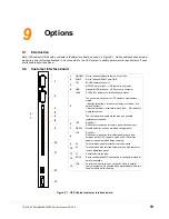
Introduction
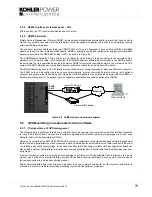
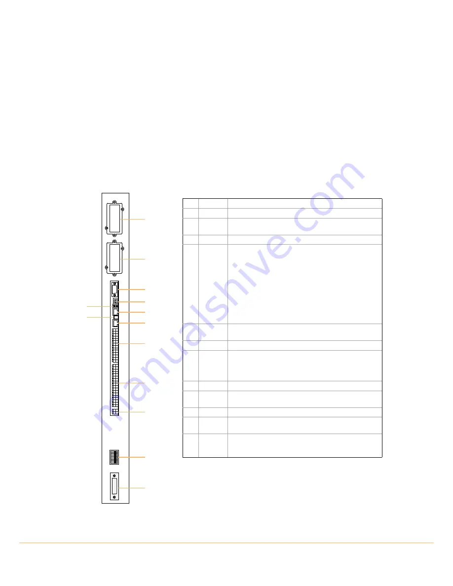
Each UPS cabinet is fitted with a customer intKohlererface board, as shown in Figure 9.1, which enables various external
monitoring and control applications to be connected to the UPS system to satisfy particular site requirements. These
interfaces are described below.
9.2
Customer interface board
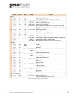
Figure 9.1 UPS Cabinet customer interface board
1
2
3
4
6
8
9
10
11
12
13
5
7
1
MODEM Slot for optional Modem/Ethernet card ONLY.
2
SNMP
Slot for optional SNMP card ONLY.
3
JD1
Sub D9 female connector
RS232 User interface – UPS system to computer.
4
USB
Standard USB interface – UPS system to computer.
5
LEDs
2 LEDs that indicate the interface board status.
The green led indicates the UPS cabinet’s master/slave
status.
– flashing twice/sec = interface is master (1st cabinet of a
parallel system).
– flashing once/sec = Interface is slave (2nd,.. 5th cabinet of
a parallel system).
The red indicates a board malfunction and possible
replacement required.
6
JR3
RJ45 Port
RS485 communication for remote panel (touch-screen).
7
DIP SW
Module selection used by multidrop configuration.
8
JR2
RJ45 Port
RS485 communication for multidrop cable connected
between all the UPS cabinets. Used with RJ45 splitter
adapter to enable module daisy chaining.
9
X3
Terminal block used for external customer inputs.
10
X2
Terminal block with volt-free outputs for use with customer
remote indications panel.
11
X1
Castell interlock function.
12
SW1-9
9-pole configuration DIP switch used to configure module for
parallel operation.
13
JD8
Parallel communication bus connector. Used in parallel
cabinet system only, and fitted with parallel adapter board to
enable module daisy chaining.