

TS_622_02 PowerWAVE 9500DPA User Manual 26/2/19
61
:
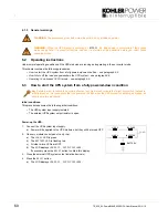
Start the UPS module(s):
5. Carry out steps 6 to 12 for each UPS module in turn.
6. Close the bypass fuse (F2).
7. Close the parallel isolator switch (IA2).
8. On the module control panel, simultaneously press both
ON/OFF
buttons.
The UPS module will begin to power up over approximately 60s.
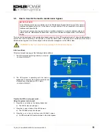
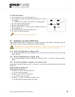
9. On the module control panel, after 60s verify that:
a) The
LINE
2
LED is green (red during initial start-up).
b) The
BYPASS
LED is green.
c) The
INVERTER
LED is red.
d) The
BATTERY
LED is flashing red.
e) The LCD displays
LOAD
NOT
PROTECTED.
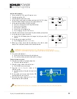
10. Close the module’s battery fuse (F3) and the external battery enclosure fuse.
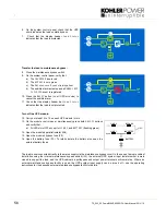
11. On the module control panel, verify that:
a) The
BATTERY
LED flashes green then changes to a solid green within 5
minutes.
12. On the module control panel, verify that:
a) The LCD displays
PARALLEL
SW CLOSED
.
13. Before you continue, ensure that the indications on the module control
panels of ALL modules are identical, and as described above.
14. Turn on the load equipment.
a) The load is now powered through the static bypass.
b) The module control panel mimic indications do not change.
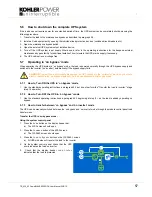
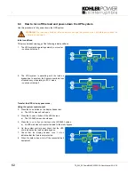
Transfer the load to inverter:
15. Press the
Home
button on the display header bar.
a) The
HOME
screen should open.
16. Press the
Command
button of the
HOME
screen.
a) The
COMMAND
screen should open.
17. Press the
Load
to
Inverter
button on the
COMMANDS
screen
a) All UPS modules will transfer the load to the
inverter
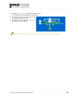
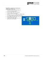
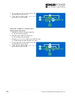
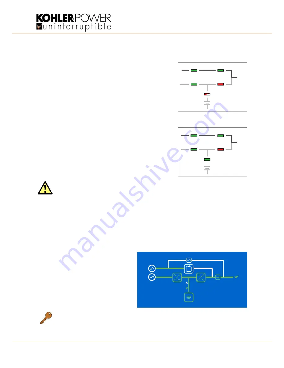
18. On the system control panel check that the UPS
mimic indicates the load on inverter.
19. Check that the display header bar
Load
Status
indicates that the load is protected.
CAUTION:
Do not proceed unless the
BYPASS
LED is green on ALL UPS modules.
If any
BYPASS
LED still fails to light green, repeat step 5, then seek trained advice if necessary
Key Point:
The UPS system is now operating in its ‘on-inverter’ mode and the load is fully protected.
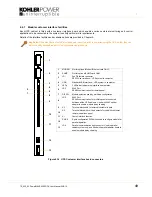
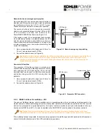
LINE 1
LINE 2
BY PASS
INVERTER
BATTERY
LOAD
LINE 1
LINE 2
BY PASS
INVERTER
BATTERY
LOAD
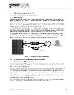
L.2
L.1
rectifier
inverter
load