

50
TS_622_02 PowerWAVE 9500DPA User Manual User Manual 26/2/19
5
Operating Instructions 1
(for systems with a maintenance bypass)
5.1
Introduction
5.1.1 Commissioning
The PW9500DPA UPS is a high quality, complex electronic system which must be commissioned by an authorised Kohler
Uninterruptible Power Ltd. engineer before it is put into use.
The commissioning engineer will:
• check the UPS electrical and mechanical installation, and operating environment
• install and connect the UPS batteries
• check the UPS configuration settings
• check the installation and operation of any optional equipment
• perform a controlled UPS start-up
• fully test the system for correct operation
• provide customer operator training and equipment handover
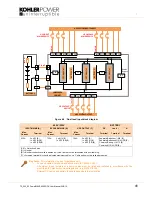
5.1.2 Operating procedure summary
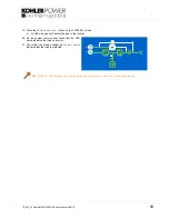
Under normal circumstances all the UPS modules in a multi-module system are turned on and operating in their ‘on-
inverter’ mode. If one module fails in a ‘redundant module’ system the faulty module shuts down but it will not affect the
remaining module(s), which will continue to operate normally and provide protected load power. The failed module can be
replaced by a trained UPS service engineer without affecting the operation of the UPS system.
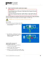
If a UPS module fails in a ‘capacity’ rated (or single module) system, the load will immediately transfer to the static bypass
(in all modules) and will be connected to the unprotected bypass mains power supply.
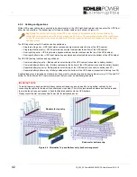
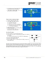
A parallel-cabinet UPS system requires an external maintenance bypass facility which wraps around the entire UPS
system – this is optional in a single cabinet installation. The external maintenance bypass is bespoke to the installation
and can be installed in a separate cabinet or switchgear panel
(see paragraph 4.5.3)
. If an external maintenance bypass is
installed you should familiarise yourself with its operating procedures before using the UPS operating procedures
contained in this chapter.
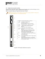
Note: All the switches and control panel operations mentioned in this chapter are identified and described in chapter 2.
IMPORTANT NOTE
This chapter contains the operating instructions that should be used if the UPS system contains the
‘optional’ Maintenance Bypass facility – i.e. if the internal Maintenance Bypass Switch is fitted in the
UPS cabinet or the UPS is connected to an external bespoke Maintenance Bypass switch panel.
If the UPS system design does not include a Maintenance Bypass facility you should use the operating
instructions contained in Chapter 6.
WARNING:
Kohler Uninterruptible Power Ltd. will not accept responsibility for the equipment or the safety of
any personnel if the UPS system is operated before it has been fully commissioned.
The manufacturer's warranty will be invalidated if power is applied to any part of the UPS system before it has
been fully commissioned and handed over to the customer.
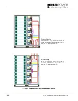
CAUTION:
In a multi-cabinet system the UPS cabinet’s internal maintenance bypass switch (IA1) is usually
removed.