


TS_622_02 PowerWAVE 9500DPA User Manual 26/2/19
21
3
System Control Panel
3.1
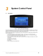
Introduction
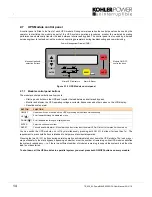
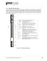
Figure 3.1 System control panel default display
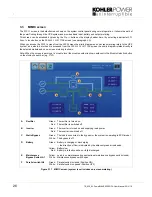
The system control panel contains a microprocessor-based TFT touch-screen display which enables you to monitor and
operate the UPS installation at a ‘system’ level. Only one system control panel is fitted to a multi-cabinet system – usually
installed on the door of the cabinet that contains the ‘master’ UPS module (Module 01).
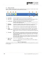
The system control panel displays the operational status of the overall UPS system as well as that of each individual UPS
module. It enables you to:
• view the input/output/battery operating parameters (voltage, current, frequency etc.) for the entire system
• view the input/output/battery operating parameters (voltage, current, frequency etc.) for a selected UPS module
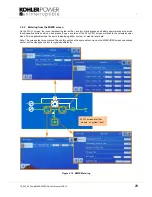
• execute a load transfer between inverter and bypass, and vice-versa
• monitor the power flow through the UPS system or selected UPS module, through an illuminated, colour-coded
mimic diagram
• check alarm and events histories
• acknowledge an event occurrence
• silence alarms
• monitor the battery state and autonomy time