


TS_622_02 PowerWAVE 9500DPA User Manual 26/2/19
15
:
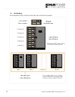
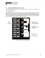
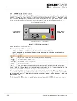
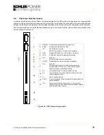
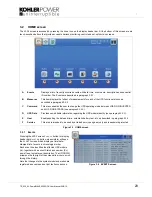
2.7.2 Mimic LED Indication
The mimic diagram LEDs indicate the general power flow through the UPS module and changes colour between Green
and Red (and OFF) to indicate the prevailing UPS module operating conditions.
* The ALARM LED is a visual indication of an internal or external alarm condition. When activated, it is accompanied by an
audible warning which can be cancelled by pressing the RESET button.
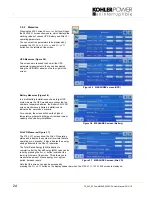
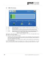
2.7.3 Power Management Display (PMD)
A 2 x 20 character LCD Display simplifies communication with the UPS module and provides monitoring information.
The menu driven LCD provides:
• Access to an ‘event’ register
• Input and output voltage, current, frequency & power monitoring
• Battery run time monitoring
• Access to commands such as module load transfer between
INVERTER
and
BYPASS
• Access to the module’s diagnostics registers (service mode only)
• Access to module adjustments and testing (service mode only)
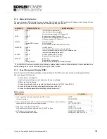
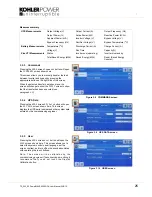
Status screens
INDICATOR
INDICATOR STATUS
INTERPRETATION
LINE 1
GREEN
RED
OFF
Input (rectifier) mains available
Input (rectifier) mains unavailable
No input (rectifier) supply (UPS Turned off)
LINE 2
GREEN
RED
OFF
Bypass mains available (bypass OK)
Bypass mains unavailable (bypass supply error)
No bypass supply (UPS Turned off)
ALARM*
OFF
Flashing RED + buzzer
RED
No alarm condition
Alarm condition
Alarm condition present (audio has been reset)
INVERTER
GREEN
RED
YELLOW
OFF
Load on inverter
Inverter fault or load transfer to inverter inhibited
Inverter in standby mode (valid for Xtra VFI operation only)
Inverter not operating (switched off)
BY-PASS
GREEN
OFF
Load on bypass (or in ECO mode)
Bypass not operating (turned off)
BATTERY
GREEN
RED
Flashing GREEN
Battery OK
Battery faulty or discharged
Battery on load (discharging) or battery fuse open
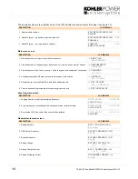
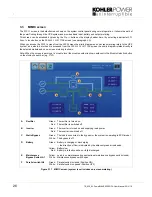
DESCRIPTION
LCD-DISPLAY
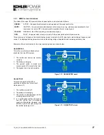
1. Load is protected and being supplied by the UPS inverter
(Normal Operation).
LOAD
PROTECTED
01
2. Load is not protected by UPS. It is either connected to the bypass (load on bypass) or
connected to the inverter but with a battery problem.
LOAD
NOT PROTECTED
01
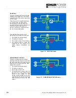
3. Load supply completely powered-down.
UPS modules have all been switched off by “ON/OFF” buttons.
LOAD OFF
SUPPLY FAILURE
01
4. UPS module is not supplying load.
The UPS output switch (IA2) is open.
LOAD DISCONNECTED
PARALLEL SWITCH OPEN
01