

:
22
TS_622_02 PowerWAVE 9500DPA User Manual 26/2/19
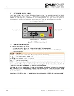
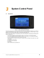
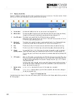
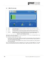
3.1.1 Display Header Bar
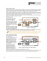
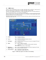
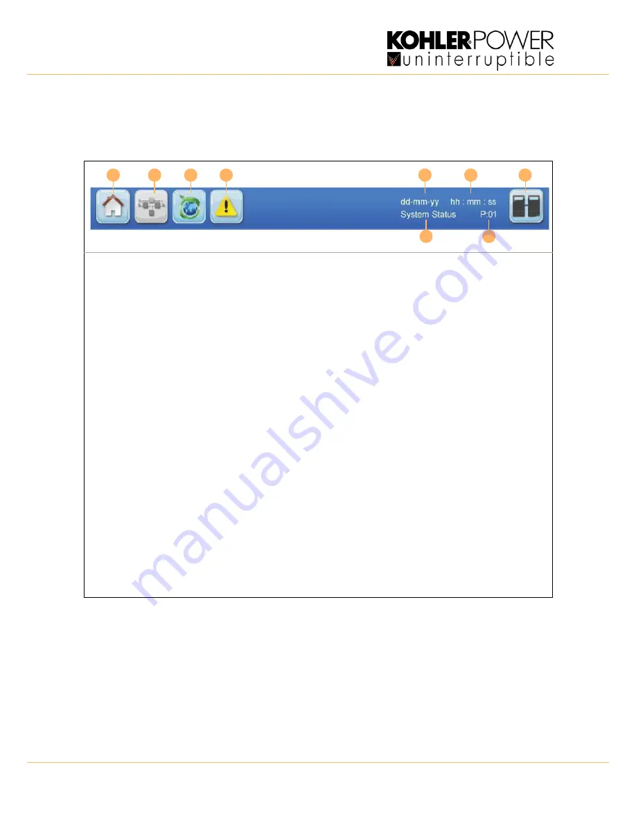
Figure 3.2 illustrates the display header bar that is presented at the top of every screen. It contains number of touch-
sensitive icon buttons, and also displays some key system status information.
Figure 3.2 Display header bar
A detailed description of each of the screens accessed by each of the buttons on the Display Header Bar is provided on
the following pages.
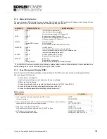
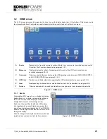
A
Home button
Accesses the HOME screen from any other screen
(see paragraph 3.2)
.
B
Mimic button
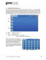
Accesses the MIMIC diagram screen which shows the shows the path of the power flowing
through the UPS system and indicates its operating status
(see paragraph 3.3)
.
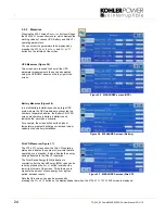
C
Xtra VFI button
This button is only visible if the Xtra VFI function has been activated.
Pressing this button toggles between the
EXTRA
VFI
MEASURES
screen and the
EXTRA
VFI
STATUS
BAR
screen
(see paragraph 3.4)
.
D
Warning &
Event button
This button is only visible if an alarm or newly monitored event occurs. Pressing this button
will silence the audible alarm and open the
EVENTS
screen
(see paragraph 3.2.1)
.
E
Date
The date is set in the
USER
screen menu and used to date-stamp the alarms/events log.
F
Time
The time is set in the
USER
screen menu and used to time-stamp the alarms/events log.
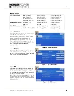
G
Module
selection button
Accesses the
MODULE
SELECTION
screen from where it is possible to select an individual
module and observe status and measurements data at module level
(see paragraph 3.5)
.
This icon changes to red if there is an active fault or event associated with an individual UPS
module.
H
UPS number
When the UPS system is commissioned, each UPS module is given a sequential ID number.
The number shown on the display header bar is used to identify the module associated with
the data currently being displayed on the system control panel screen (e g.
P:01
= module 1
in the example shown).
No UPS number will be indicated, and this area of the display header bar will remain blank, if
the module control panel is displaying ‘system’ level parameters, such as the system mimic
screen, measurements screens etc.
I
System status
OR
Load Status
System status
: indicates that the user is in the system level navigation.
Load status:
displays whether or not the load is protected, when the user is viewing at
the module navigation level.
A
B
C
E
F
G
I
D
H