background image

37

Spare parts

AZURA®  CT 2.1 Service Instructions  VSM-020

11. Spare parts

Component

Order number for 

CT 2.1 with serial 

number lower than 

FCA183800001

Order number for 

CT 2.1 with serial 

number 

FCA183800001  

or higher

Order number for 

CT 2.1 with serial 

number FCC

...

Door sealing 8 mm

M2771

M2771

M2771

Fan plate with clips

M2772

M2772

M2354A

Door outside plate, blue M2773

M2773A

M2773A

Door inside plate, white

M2774

M2774A

M2774A

Solvent pre-heater 

system for 0.1 mm ID 

capillaries

A05852-3

Leak sensor

M2356A

Cooling/heating part 

incl. temperature sensor

G6740B

Fan inside part

M2353A

PCB main- and 

LAN-board

G1194C

Summary of Contents for Azura CT 2.1

Page 1: ...Column Thermostat CT 2 1 Service Instructions Document no VSM 020 HPLC HPLC...

Page 2: ...net www knauer net E Mail info knauer net Article number VSM 020 Version number 1 0 Last update 2020 09 22 This document contains confidential information and may not be reproduced without written con...

Page 3: ...uest form and decontamination report 8 3 Device view 9 4 Calibrating CT 2 1 manually 10 4 1 Temperature measurement 10 4 2 Calibrating CT 2 1 manually via Service tool 11 5 Door 14 5 1 Door of CT 2 1...

Page 4: ...s AZURA CT 2 1 Service Instructions VSM 020 8 Replacing the leak sensor 33 8 1 Removing the leak sensor 33 8 2 Installing the new leak sensor 35 9 Adjusting the leak sensor 36 10 Firmware updates 37 1...

Page 5: ...n the service instructions All safety instructions in the user instructions The environmental installation and connection specifications in the user instructions Only use spare parts tools and cleanin...

Page 6: ...hnical changes by the service technician such as unauthorized modifications Violations of General Terms and Conditions GTC 1 4 2 Warranty conditions For information on warranty please refer to our gen...

Page 7: ...f the service technician These service instructions are intended for the following professional groups Task Authorized Maintenance KNAUER service technicians Service technicians authorized by KNAUER w...

Page 8: ...ed in the service instruc tions and recognize and avoid possible dangers independently The ability of the technician to react is not impaired by the consump tion of drugs alcohol or medication 2 2 Ser...

Page 9: ...ce Instructions VSM 020 3 Device view 1 Cartridge for eluent pre tempering optio nal 2 Door 3 Housing 4 Column holder 5 Fan 6 Temperature sensor 7 Column not included with the delivery 8 Leak sensor 1...

Page 10: ...nt door 4 Turn on the column thermostat Fig 2 Inside view of the device 5 Enter a temperature of 30 C in the status window of the Service tool and wait for at least 30 min to equili brate the temperat...

Page 11: ...Not all three temperatures have to be entered if only one or two require correction KNAUER Service tool Procedure Figure 1 Open KNAUER Service tool finder select the oven and establish connection to...

Page 12: ...s described in chapter 4 1 and press recalculate button Note If the heat cool element has been changed as described in chapter 7 please press Set Defaults before you enter new temperature values Fig 6...

Page 13: ...1 Service Instructions VSM 020 Procedure Figure 5 Send values by pressing the red arrow on left hand side of the window and click Write information for current view into the device Fig 8 Sending valu...

Page 14: ...been removed Phillips head screwdriver 2 5 mm Process Figure Procedure 1 Loosen and remove both screws 1 on the upper retaining plate 2 of the door 2 Loosen and remove both screws on the lower retaini...

Page 15: ...er and push in the hinge 5 Remove the door 6 Be careful and fix the retaining plate of the door so it cannot fall down Fig 11 Remove door 7 Safely store the 2 white washers one at the top and one at t...

Page 16: ...hat the flat head screws have enough room Fig 13 Tightening screws 3 Put the washer back on the hinge pin of one side of the door 4 Reinstall this side of the door by pushing the hinge pin of the reta...

Page 17: ...wdriver Process Figure Procedure 1 Loosen the five cross head screws 1 at the door trim 1 Fig 16 Screws on the door trim 2 Carefully lift the door trim 2 with a flat screwdriver and remove Note Do not...

Page 18: ...he door has been removed Scissors Process Figure Procedure 1 Remove the three parts of the door seal manually 2 Measure the amount of seal that is needed on the door 3 Cut the three parts of the new d...

Page 19: ...ce the device on its side Process Figure Procedure 1 Remove the tem perature sensor 5 from the column fix ture 4 2 Loosen the 4 screws 3on the fan plate 2 3 Carefully lift off the fan grating 1 4 Remo...

Page 20: ...rx screwdriver T10 Process Figure 1 Loosen the 6 Torx screws Fig 21 Loosen the screws with a Torx screwdriver Prerequisite Tools Electronic defect Performing maintenance tasks on a switched on device...

Page 21: ...red cable on the left side of the mainboard Fig 22 Loosen the cables and plug in connectors on the mainboard 5 Loosen 3 cable ties which bundle the cables 6 Loosen the cable support 4as well and put i...

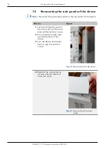
Page 22: ...of the device with the slot screwdriver to remove it Fig 25 Lift cover plate with a slot screwdriver 2 Remove the cover plate by hand 3 Repeat step one and two to remove the cover plate at the bottom...

Page 23: ...of the side panels slightly with the slot screwdriver Fig 28 Lift the overlapping sides 7 Remove the side panels on both sides of the device carefully 8 Disconnect the green groun ding cables which a...

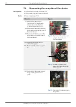
Page 24: ...river T20 length 150 mm or longer Hexagon screwdriver 8 mm Process Figure 1 Open the door of the de vice and remove the tem perature sensor 1from the column fixure 2 Lay the temperature sensor on the...

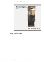
Page 25: ...of the heat cool element A greater effort might be needed 6 Turn the device around so the bottom of the device faces you Loosen the 2 screws at the bottom of the device to be able to remo ve the heat...

Page 26: ...ol element through the opening 2 Attach the black sealing between heat cool element and interior 3 Insert the heat cool element carefully with little side to side movements into the ope ning The seali...

Page 27: ...n blades 7 The cable of the temperature sensor must be placed between the cooling fins right side from the middle Fig 37 Position of the temperature sensor cable 8 Mount the fan onto the fan plate Til...

Page 28: ...Figure 11 Clip the temperature sensor back into the column fixture Ensure a space of approx 8 to 10 mm between the top of the sensor and the top edge of the fan plate Fig 39 Installed temperature sen...

Page 29: ...device Process Figure 1 Lay the overlapping ends of the side panel over the base plate and fasten the 2 screws 2 Ensure that the rubber feet are at the bottom of the device 3 Turn the device and repea...

Page 30: ...structions VSM 020 Process Figure 5 Press onto the middle of the cover plate in order to click it in place completely 6 Repeat step four and five with the bottom cover plate Fig 42 Click the cover pla...

Page 31: ...k sensor 3 8 Reconnect the black and the red cable at the lower part of the mainboard 9 Reconnect the blue and the red cable on the left side of the mainboard Fig 43 Reconnect the cables and plug in c...

Page 32: ...T 2 1 Service Instructions VSM 020 Process Figure 1 Fasten the 6 Torx screws and remount the rear plate of the device Fig 46 Fasten the screws with a Torx screwdriver The rear plate has been remounted...

Page 33: ...1 Open the door of the device 2 Gently push the leak sensor through the hole in the back of the device by using the round rod and the hammer Fig 47 Inside view of the device Prerequisite Tools Electr...

Page 34: ...g in connector for the leak sensor 1 Fig 49 Remove the plug in connector of the sensor 3 Loosen 3 cable ties which bundle the cables Ensure not to damage other cables 4 Loosen the cable support 2as we...

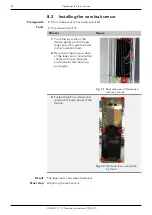
Page 35: ...w leak sensor through the hole in the insulation foam 2 Reconnect the plug in cable of the leak sensor secure the cables with new cable ties and remount the cable sup port again Fig 51 Rear side view...

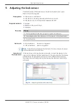
Page 36: ...25 l methanol No alarm is triggered 100 l methanol Alarm is triggered Note Open the door between the two tests for a few minutes to evapo rate the methanol of the first test If this test does not brin...

Page 37: ...Firmware updates AZURA CT 2 1 Service Instructions VSM 020 10 Firmware updates The device s current firmware is functional Via the KNAUER Service tool software LAN Prerequisites Firmware update proce...

Page 38: ...igher Order number for CT 2 1 with serial number FCC Door sealing 8 mm M2771 M2771 M2771 Fan plate with clips M2772 M2772 M2354A Door outside plate blue M2773 M2773A M2773A Door inside plate white M27...

Page 39: ...structions online www knauer net service instructions KNAUER Wissenschaftliche Ger te GmbH Hegauer Weg 38 14163 Berlin Phone Fax E Mail Internet 49 30 809727 0 49 30 8015010 info knauer net www knauer...

Reviews: