background image

Shelv- filter 

A shelv filter can be found in nearly every mixing desk, normally for low and high 
frequency adjustment. They can boost or cut a wide frequency range above (high 
shelv) or below (low shelf) the mid- frequency. Furthermore we added shelv filters 
with adjustable bandwidth (

LSQ

 and 

HSQ

) which are, corresponding to the value of 

the „Q“ facto (we recommend values between 0,4 and 4,0), either more “flat” than 
“normal” shelvs (Q=0.7) or with a higher “Q” (1.0 to 4.0) they create an useful “peak” 
around the mid frequency. 
 
Setting the bandwidth outside of Q <0,4 und Q >4,0 is 

not 

recommended. 


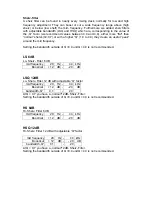
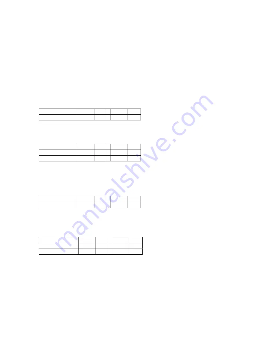
LS 6dB 

Lo- Shelv- Filter 6 dB 

mid frequency 

20  Hz  - 

44 kHz

Boost/cut 

+ 12  dB  - 

- 20

dB


LSQ 12dB 

Lo- Shelv- Filter 12 dB with adjustable “Q” factor 

mid frequency 

20  Hz  - 

44 kHz

Boost/cut 

+ 12  dB  - 

- 20

dB

bandwidth „Q“ 

0,1 

  - 

20

At Q=  0,7 you have a „normal“12dB- Shelv- Filter. 
Setting the bandwidth outside of Q <0,4 und Q >4,0 is 

not 

recommended. 


HS 6dB 

Hi- Shelv- Filter 6 dB 

mid frequency 

20  Hz  - 

44 kHz

Boost/cut 

+ 12  dB  - 

- 20

dB


HSQ 12dB 

Hi- Shelv- Filter 12 dB with adjustable “Q” factor 
 

mid frequency 

20  Hz  - 

44 kHz

Boost/cut 

+ 12  dB  - 

- 20

dB

bandwidth „Q“ 

0,1 

  - 

20

At Q=  0,7 you have a „normal“12dB- Shelv- Filter. 
Setting the bandwidth outside of Q <0,4 und Q >4,0 is 

not 

recommended. 


Summary of Contents for DAP 26

Page 1: ...User Manual DAP 26 Digital Audio Processor KME Control Remote Software Mainframe ...

Page 2: ...DAP 26 HW Version 1 2 r0026 DAP 26 MC Version 1 1 r0052 KME Control Version 1 00 Build 0073 DAP 26 Plug Version 1 00 Build 0149 Manual Rev Version 1 00 EN Stand 12 04 2005 service kme sound com ...

Page 3: ...0 CLIP 0 dB 60 0 dB 60 0 dB 60 MU TE dB 6 6 MU TE dB 6 6 MU TE dB 6 6 MU TE MU TE MU TE dB 6 6 dB 6 6 dB 6 6 K M E DAP26 V0 1 Preset Configuration Choose an option Input level meters Two 10 digit digital level meters help to set the correct input level on the analog audio inputs or to monitor the digital audio input level The graphic below shows different peak input levels on your unit a b c d a t...

Page 4: ...igation pad is to be used for accessing and changing parameters on the display of the hardware unit Press the OK button if you are asked by the software See also the appendix menu structure Level meter 1 6 Level correction 1 6 Mute switch 1 6 LIMIT 0 dB 60 MUTE dB 6 6 MUTE dB 6 6 The level correction pot adjusts the output level of the corresponding channel by 6 dB This is done on digital signal l...

Page 5: ...he dynamic processor Compressor Limiter is activated and works Mains switch Use this switch for powering up the hardware unit We included a power up delay which prevents clicks or plops in the speakers efficiently nevertheless we recommend switching on your power amplifiers after the DAP The backlighting of the display shows that the DAP is switched on and the mains power is within the useable ran...

Page 6: ... inputs of the DAP 26 are electronically balanced Unless it is necessary we do not recommend unbalanced audio connections The inputs have to be operated with an nominal audio level of either 775 mV 0 dB or 1 55V 6 dB which you can select using the switch beside the connector b corresponding to the signal level your source units work with 1 2 3 1 2 3 XLR to XLR balanced audio connection 1 2 3 Jack ...

Page 7: ... ˆ Follow this navigation scheme to activate the analog audio inputs factory preset after using the digital audio input sometimes This is one of the few settings that can only be done on the hardware unit itself Analog outputs 1 6 O U T P U T 6 4 2 5 3 1 The analog audio outputs 1 6 are electronically balanced male XLR sockets We do not recommend connecting unbalanced destination devices to the DA...

Page 8: ...r connector labelled RS232 CAN Make sure that the yellow LED beside the connector GLOWS BEFORE connecting the unit to your PC If the LED does NOT glow operate the switch which is located just below this LED using a suitable tool You can now run the KME Control software and activate the communication see software 1 5 3 2 4 7 8 9 6 1 5 3 2 4 7 8 9 6 9 pole D sub cable 1 1 as supplied with the DAP 26...

Page 9: ...interface to your DAP 26 using the supplied or a modified cable Connect the supplied CAN terminator plug to the lower socket of your DAP 26 If there are more DAPs daisy chained connect the CAN terminator plug to the free connector of the last device in your CAN chain You can now run KMEControl software and activate the communication see software 1 5 3 2 4 7 8 9 6 1 5 3 2 4 7 8 9 6 CAN Bus Link cab...

Page 10: ... to AES EBU with a bit rate of 16 to 24 and a sampling frequency of 32 to 96 kHz using an internal format sample rate converter chip The digital audio output loops the selected input analog digital as a 24 bit 96 kHz AES EBU signal for cascading additional units or recording the signal to a studio digital recorder All digital connections are transformer balanced for maximum protection against grou...

Page 11: ...64V AC 50 60Hz CAUTION PULL PLUG BEFORE OPENING Connect the supplied mains power cable to this socket If the supplied cable is not conform to your local mains allocation use another cable which fits to the necessary specification or ask a technician to change the mains plug The DAP 26 works with all types of mains power between 100 and 250 volts without pre selection If the fuse breaks replace it ...

Page 12: ...Master Mute Gain Channel 1 3 Value 60 dB 10 dB Gain in the input and all output channels routed to this input channel Master Gain The output level pots are to be used independently Filters Channel 1 3 Filter 1 5 Type Filter type see chapter Filters Frequency 20 Hz 44 kHz Q bandwidth 0 1 20 Gain boost cut 20 dB 12 dB Equalizer of the Input and all output channels routed to this input Master EQ This...

Page 13: ...pending HP Type Bypass Butterworth Linkwitz Riley Bessel HP Freq 20 Hz 44 kHz HP Order 1 8 filter depending Frequency crossover networks for the different output channels Using a single filter low pass or high pass or a valid combination of both filter banks band pass a powerful tool for controlling PA systems is given to the user The user can select a filter of the types Butterworth Bessel and Li...

Page 14: ...ogram material The attack release time draw the speed of the gain regulation mechanism A longer attack time will let some signal peaks pass which may sound more powerful a short attack time will give more protection to the speakers A longer release time is advantageous for maximum protection of speaker components on the other hand a short release time increases the average sound level using the co...

Page 15: ...ctor factor octaves 0 5 2 9 Narrow 0 4 3 0 wide 1 0 1 4 1 4 1 0 1 5 0 9 2 4 0 6 2 0 0 7 wide 4 4 0 3 narrow Parametric filters The so called parametric filters are widely used in professional audio equipment for example in mixing desks or speaker processors The curve of this filter is described with certain parameters mainly the centre frequency the bandwidth and the gain boost cut of the filter C...

Page 16: ... to set the value for Q between 0 4 wide 1 4 normal 4 0 narrow Higher lower Q values are not recommended unless the user has enough knowledge using this special filters PEQ II Parametric Equalizer Type II Full parametric equalizer like the types known from mixing desks Centre frequency 20 Hz 44 kHz Boost cut 12 dB 20 dB bandwidth Q 0 1 20 It is recommended to set the value for Q between 0 4 wide 1...

Page 17: ...ency Setting the bandwidth outside of Q 0 4 und Q 4 0 is not recommended LS 6dB Lo Shelv Filter 6 dB mid frequency 20 Hz 44 kHz Boost cut 12 dB 20 dB LSQ 12dB Lo Shelv Filter 12 dB with adjustable Q factor mid frequency 20 Hz 44 kHz Boost cut 12 dB 20 dB bandwidth Q 0 1 20 At Q 0 7 you have a normal 12dB Shelv Filter Setting the bandwidth outside of Q 0 4 und Q 4 0 is not recommended HS 6dB Hi She...

Page 18: ...es High Cut Setting the bandwidth outside of Q 0 4 und Q 2 0 is not recommended HP High Pass Filter 12 dB with adjustable Q factor mid frequency 20 Hz 44 kHz bandwidth Q 0 1 20 At Q 0 7 you have a normal low pass filter like you find it in some professional mixing consoles Lo Cut Setting the bandwidth outside of Q 0 4 und Q 2 0 is not recommended BP Bandpass Filter with adjustable Q factor The ban...

Page 19: ...nd the bandwidth With a Q factor above 5 this filter is very narrow allowing the user to filter out unwanted frequencies i e mains hum at 50 Hz and certain harmonics completely With a Q factor below 5 the filter response is quite wide but this set up is seldom used in professional audio systems mid frequency 20 Hz 44 kHz bandwidth Q 0 1 20 ...

Page 20: ...ass filtering may not damage the sound system but affect the sound in a negative way The mode of action is presented here AP I All pass filter Type I This filter creates a quite flat smooth phase shift over the whole frequency range with a characteristic 90 pole at the centre frequency mid frequency 20 Hz 44 kHz AP II All pass filter Type II This filter creates a steep phase shift at the centre fr...

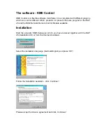
Page 21: ...ug ins for the DAP 26 and the RCM Network Remote Control Module available Installation Start the program KME Setup exe which you have received together with the DAP 26 Installation CD or from the Internet download Select the installation language German English and press OK Follow the installation assistant click Continue Please accept the licence agreement and click Continue ...

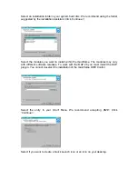
Page 22: ...ant to install within the mainframe The modules may vary with different software releases To work with the DAP 26 you must install the DAP plug in You cannot deselect the installation of the mainframe KME Control Select the entry in your Start Menu We recommend accepting KME Click Continue Select if you want to create a Quick Launch icon or an icon on your desktop ...

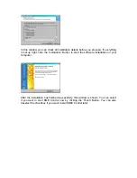
Page 23: ...lick the Installation Button to start the software installation on your computer After the installation has finished successfully this window is shown You can select if you want to start KME Control now by clicking the Finish Button You can also deselect the checkbox if you want to start KME Control later ...

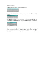
Page 24: ...rying to install a new plug in or update We also recommend closing all other programs during an installation process of new software If you receive this message you can select Yes without caring about your user presets stored in this folder to be deleted They will not be deleted even by de installation of the software To erase the software completely from your computer this folder has to be delete...

Page 25: ...indow The plug in may be activated more than once in the actual release you can select up to four active windows limited to screen capabilities In RS 232 mode you can connect up to four DAP units to your computer if enough COM ports are present By adding the CAN Bus option the user is able to use up to 63 hardware units on one host computer Refer to the CAN Bus part of this manual for additional i...

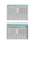
Page 26: ...Example Connecting two DAP 26 on different COM ports ...

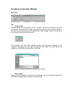
Page 27: ...st changes select No and save your preset to disc using Save Preset If you choose Yes the Open dialogue window will be opened Navigate to the location of the preset file you want to load and click Open The only files to be loaded are KPF which means K M E preset file Select the preset you want to load and click Open Save Preset Saves your actual preset to a disc of your computer You can send this ...

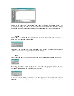
Page 28: ...ppears to ask if you want to save your last changes to the preset Selecting Yes opens the Save dialogue No closes the plug in window and Cancel returns to the plug in window without changes Exit Terminates the KME Control mainframe You will be asked if you really want to exit Selecting No returns to the program Yes terminates the program If there are data unsaved you will be asked to save or disca...

Page 29: ... Setting a password is quite easy Go online to the connected DAP 26 first and then select Set password The following window should appear Enter a 4 digit only numbers are accepted password in the field New password Enter the password again into the field Confirm password and press OK Your DAP 26 is now password protected When trying to connect the DAP 26 to the computer again you are asked for the...

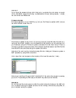
Page 30: ...Firmware update procedure from the main menu If there is a firmware update manual included to the firmware download please read this file first and follow the manual whilst doing the update procedure Attention The unit must be connected using RS 232 COM port Firmware update is NOT possible by using CAN connection Click Open File and navigate to the location of the new firmware file mhx Klick Open ...

Page 31: ...igurations for various PA applications They include routing and crossover standard settings for all channels This may save time creating new set ups To load a set up from the list just click on it You are being asked if you want to overwrite the actual preset Select No if you want to save your actual preset first Selecting Yes loads and initialises the selected set up The different quick set ups a...

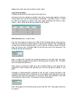
Page 32: ...ows the version number and revision of the DAP 26 plug in This information may be required contacting the K M E support Click OK to close this window or click the blue link to visit the K M E homepage requires active Internet connection ...

Page 33: ...e software and initialise the communication again If you forgot the password you will have to send the hardware unit to the K M E support for factory re initialisation Please refer also to the chapter Set password of this manual If everything is OK with the communication the following window will appear showing that data is exchanged between the DAP 26 and your PC If the connection is set up you a...

Page 34: ...settings on the hardware unit you have to go Offline pressing the Disconnect button Clicking into the Preset list box allows the user to load another preset into the software plug in by selecting one out of the list The selected preset will be loaded When you have made your changes to the preset you can save the preset in the hardware unit by clicking the store preset button The software sends the...

Page 35: ... time you want to use your computer programming a DAP 26 Try using another COM port or use a USBtoRS232 converter connected to the USB port of your computer You are using the wrong cable Solution Do only use cables according to the K M E specification to avoid communication errors or even damages of both the DAP 26 or your computer You are using the wrong communication port on the DAP 26 Solution ...

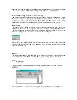
Page 36: ...the selected channel affected by crossover networks and or filters This tab includes drag and drop functionality with the mouse Phase The tab Phase is active within the modules Equalizer and Crossover and shows the phase response of the selected channel affected by crossover networks and or filters Drag and drop is deactivated on the Phase tab Dynamic The register tab Dynamic is activated in the d...

Page 37: ...The values are stored in the hardware unit and can be read out by other users Gain In this window the input output levels can be either set by mouse writing the specified gain value in the dB field or using the cursor keys for fine adjustment of the pre selected fader You can operate the Mute buttons Polarity switches and Stereo link Mute all buttons as desired Delay ...

Page 38: ... each channel you may combine any 5 filters of the available filter types The filter types are described in the chapter filters To activate a filter first select the channel in which you want to add the filter by selecting a register card Then activate one of the 5 filters by clicking into the grey Bypass field below the red field labelled Filter X This field will change to green to signalise the ...

Page 39: ...er It is possible to move this points with the mouse and monitor the acoustic changes in real time after releasing the mouse button when the DAP26 is online Here is an example how to create a classic mixing desk type equalizer using the filter banks of the DAP 26 ...

Page 40: ...Filters 1 4 are to be set to the values specified below The remaining filter could be used as a Low Cut i e at 80 Hz ...

Page 41: ...ow in the routing matrix see below To assign an output to a bass channel simply activate the High Cut Filter by clicking into the grey Bypass button below the red control field labelled High Cut This field will change to green when the filter is activated We recommend using the filter type Linkwitz Riley for any standard crossover applications For this example set the filter frequency to 120 Hz Th...

Page 42: ...channel 2 using the Copy Parameter dialogue or setting it manually To operate channels 3 4 as Mid High outputs proceed as described above but use the Low Cut Filter instead using the same parameters This setting would look like this As you can see the output channel 1 contains only the bass frequencies below 120Hz ...

Page 43: ... section when you are online with the DAP 26 and a sound system is connected and running In this case all settings are transmitted to the DAP in real time and a wrong filter may damage the speakers Dynamik In this window you can activate the dynamic processing units of all output channels To activate a dynamic processor simply select the register card of the channel you want to process and click t...

Page 44: ...or begins to control the level according to the compressing Ratio selected If the ratio is i e 4 1 then the level has to increase by 4 dB to allow the output increasing by 1 dB This is the compression mentioned With higher ratio settings the compression will be more audible which must not be negative at all The Knee value describes the point where the compression starts A knee value of 0 starts th...

Page 45: ...level above the threshold is allowed to pass Limiters are used for maximum protection of speaker components or maybe for securing maximum sound pressure levels prescribed by law The Knee value is comparable with the compressor too Higher knee values allow to start limiting more softly normally less audible ...

Page 46: ...ection together with the output level of the selected channel c Noisegate The noise gate can be activated by clicking into the grey Bypass field The threshold slider will occur and the control field will change the colour to green when the noise gate is activated The operation is easy just set the threshold level the minimum sound level above i e disturbing background noise All audio material with...

Page 47: ...pass OK Change value ˆ PrXX In Fil ChA Q 0 7 OK Change value ˆ PrXX In Fil ChA Frequency 1000Hz OK Change value ˆ PrXX In Fil ChA Gain 0 0dB OK Change value ˆ PrXX Inputs Filter Choose an option PrXX In Filter Channel A Choose a Channel Preset XX Inputchannels Choose an option Deviceinfo Revision X X Choose an Info ˆ Deviceinfo S N 123456 Choose an Info ˆ K M E DAP26 Deviceinfo Choose an option ˆ ...

Page 48: ...nverters 128 x Oversampling Digital input AES EBU SPDIF with Format Sample rate converter Dynamic range Analog Input to Output 108 dB A Distortion THD 0 001 Preset Memory User presets 32 Software for PC mit Windows 2000 XP PC connection serial RS 232 9 pin details displays 8 digit LED chains for inputs and outputs backlighted LCD Display knobs Navigation pad mains switch Gain pots Special features...

Page 49: ...For your notes ...

Page 50: ......

Page 51: ......

Page 52: ...48 Klingenthal Germany phone 49 0 37467 558 0 fax 49 0 37467 558 33 www kme sound com service kme sound com Technical State February 2005 The content corresponds to the state at printing Subject to technical alterations Misprints and errors expected Feb 2005 SL ...

Reviews: