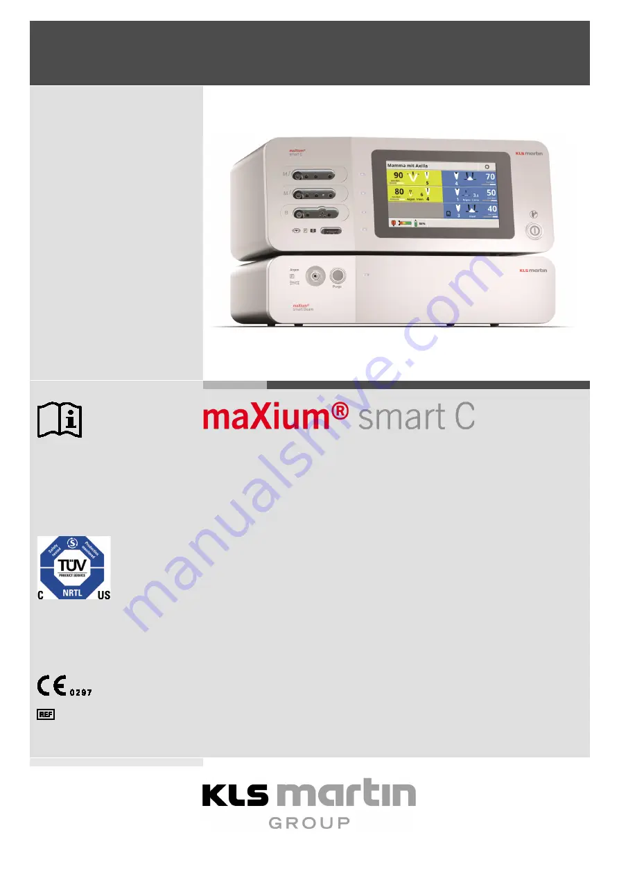
KLS Martin maXium smart C Instructions For Use Manual Download Page 1


Front Cover 


English 


Tested according to: 
UL 60601-1:2003 
CAN/CSA C22.2 No.601.1-M90


maxium® smart C Electrosurgery Unit with 

maxium® smart Beam 


Instructions for Use 


 90-046-52-10 

Revision 1 

Date of Release: 2017-10 

Valid from software version V1.3.35.3017 


Summary of Contents for maXium smart C

Page 1: ...d according to UL 60601 1 2003 CAN CSA C22 2 No 601 1 M90 maxium smart C Electrosurgery Unit with maxium smart Beam Instructions for Use 90 046 52 10 Revision 1 Date of Release 2017 10 Valid from soft...

Page 2: ...a situation which if not avoided will result in death or serious injury Follow Instructions for Use Reference number for ordering Gebr der Martin products item number Serial number Store in a dry pla...

Page 3: ...on for the neutral electrode Neutral electrode insulated against ground floating Symbol for classification of the unit as type CF The unit is defibrillation proof CAUTION High voltage high frequency c...

Page 4: ...Preface 13 4 2 Monopolar application of HF current 14 4 2 1 Monopolar cutting 14 4 2 2 Monopolar coagulation 14 4 2 3 Neutral electrode 15 4 3 Bipolar application of HF current 16 4 3 1 Bipolar cutti...

Page 5: ...Use of two electrosurgical devices on one patient 29 6 Functions 29 6 1 Overview 29 6 2 Connections on the Front 32 6 2 1 Monopolar connections 32 6 2 2 Bipolar connections 33 6 2 3 Neutral electrode...

Page 6: ...rgon Filling Level 51 9 7 Automatic Functions of Bipolar Coagulation 51 9 8 Information about the limitations of the auto start function 52 10 Using the maxium smart C 53 10 1 General Information 53 1...

Page 7: ...essages during Self Test 107 13 2 Messages in Case of Activation Errors 109 13 3 Input Feedback 110 13 4 Messages in Connection with Programs 111 13 5 Messages from the Argon Beamer and the Fume Sucti...

Page 8: ...t all personnel handling the product have understood and do observe the notes and instructions in this document Every user is required to read this document completely and follow it carefully In parti...

Page 9: ...ly implemented This ensures that it is always clear which software statuses are covered by this document 1 4 Symbols Used in this Document Throughout this document important information such as genera...

Page 10: ...9 7461 706 193 info klsmartin com www klsmartin com 2 2 Hotline Should you have any questions on how to handle the unit product or question on its clinical application please do not hesitate to contac...

Page 11: ...or maxium smart Cart REF 80 048 01 04 Isolating transformer maxium smart Cart REF 80 048 02 04 Device holder for maxium smart devices REF 80 048 03 04 Gas cylinder holder for maxium smart Cart REF 80...

Page 12: ...pliance will void any liability claim against Gebr der Martin 3 Intended Use 3 1 Intended use of the maxium smart C The maxium smart C electrosurgery unit hereinafter referred to as the maxium smart C...

Page 13: ...igh frequency HF electricity has been known for more than a century As early as the 1890s Tesla Nernst and d Arsonval conducted first experiments into the physiological effects of currents with high f...

Page 14: ...s Unintended concentrations of the current density may result This is why the anatomical features of the operation field and its surroundings must be taken into account Moreover the current flowing th...

Page 15: ...able electrodes The neutral electrodes consist of soft electrically conductive plastic material which can easily adapt to the body contour The reusable neutral electrodes are equipped with a permanent...

Page 16: ...roblems resulting from formation of an extensive flow field are avoided in bipolar application 4 3 1 Bipolar cutting In contrast to monopolar cutting in bipolar cutting the HF current flows as in bipo...

Page 17: ...c interference from electrosurgical devices may disturb or completely block pacemakers or other active implants For further information refer to section 5 5 page 25 5 1 Risks from Stray Currents In th...

Page 18: ...ing and contact coagulation currents are used while it is very low in purely bipolar application 5 1 2 High frequency leakage currents Wherever a circuit conducts high AC voltage against the ground po...

Page 19: ...larly high where high voltage monopolar currents are used and in particular with cutting currents and sparking coagulation currents With the bipolar currents of the maxium however it is low 5 1 4 Meas...

Page 20: ...ering the patient from the active electrode seems to decrease very quickly from the contact point of the active electrode the HF current then flowing to the neutral electrode at low current density In...

Page 21: ...scle layer with good conductivity in the electrosurgical sense However in the area of the upper limbs which are a preferred application site for the neutral electrode particular in obese patients ther...

Page 22: ...ffected Particularly for longer operation times it must be made sure that the patient does not lie on the cable connection clip of the neutral electrode risk of pressure necrosis The current paths in...

Page 23: ...Under a normal atmosphere these substances are usually self extinguishing and cannot be ignited by the arc at the active electrode Under an oxygen rich atmosphere however they are combustible unless m...

Page 24: ...ssor in practice arcing of the surgical glove occurs frequently at the point where the compressor is held The high voltage coagulation currents may cause corona discharges between the supply cable of...

Page 25: ...tored using suitable technology A defibrillator as well as an external pacemaker should be kept ready for use Select the lowest possible output power on the electrosurgery unit Do not use the active e...

Page 26: ...argon into the underlying tissue emphysema In tissue structures where a skin layer is located above a closed tissue layer or which several layers of skin overlay each other argon may be insufflated be...

Page 27: ...its inertness argon unlike carbon dioxide which is also used in medical technology does not affect gas exchange in the lungs but it can displace the respiratory air if the concentration becomes very...

Page 28: ...ing it to an integrated electromedical system attention must be paid to the following points Accessories to be connected to the analog and digital interfaces of the unit must demonstrably satisfy the...

Page 29: ...field The total power of the simultaneously applied currents must not exceed 400 W 6 Functions 6 1 Overview The maxium smart C is a microprocessor controlled high frequency surgery device according to...

Page 30: ...ns for Use maxium smart C Electrosurgery Unit with maxium smart Beam 30 Revision 1 e i m socket modules Fig 6 1 maxium with m i and e socket modules Symbols on maxium smart C Refer to Symbol Explanati...

Page 31: ...t port 9 Channel display Coagulation for bipolar HF output port 10 Channel display Coagulation for monopolar HF output ports 11 Selection Service Setup 12 ON OFF key 13 Display VAC connected 14 Status...

Page 32: ...plain 4 mm connector banana plug For this plug use the right socket Insertion into either of the neighboring control contacts will cause malfunction Risk of injury from unauthorized accessories On th...

Page 33: ...ol contacts will cause malfunction 6 2 2 Bipolar connections The socket of the socket module of the m version is suitable for standard instruments by Gebr der Martin The socket can be used to connect...

Page 34: ...Rear 6 3 1 Foot switch connections Two foot switches can be connected to the maxium smart C One double pedal foot switch at the connection socket 18 Fig 6 1 one single pedal foot switch at the connec...

Page 35: ...usly with the regular use In addition the installation and version notes of the manufacturers of these systems apply Other PC systems may be connected only for servicing and as long as the device is n...

Page 36: ...m smart C is set to display the last used program after each switching on However in the Service menu the base program can be defined as autostart program factory default see section 10 6 7 Service pa...

Page 37: ...nal spray coagulation During cutting argon can flow around the cutting electrode as a shielding gas displacing atmospheric oxygen and thereby reducing the formation of combustion products In both case...

Page 38: ...applicators comprise particularly thin lumens The gas flow is activated synchronously with the HF current Here the maxium smart C which also supplies power to the maxium smart Beam activates the latt...

Page 39: ...ive cap from the angle valve and screw on the pressure reducer Tighten the knurled screw only as far as manually possible without effort Only then open the angle valve of the cylinder at least half a...

Page 40: ...h a purity of more than 99 998 This purity is per se not required for the process of the maxium smart Beam But only these high purity gases primarily intended for analytics are filled into pressure cy...

Page 41: ...rilizable applicator which will hold back potential germs with the exception of viruses 7 2 Instruments Electrode Handles Electrodes Foot Switches and Cables for maxium and maxium smart Beam The maxiu...

Page 42: ...ng network then this can be done using the connection pin on the rear via the equipotential bonding cable REF 80 260 50 04 This cable is optional and not included in the scope of delivery of the maxiu...

Page 43: ...stem components are stacked one upon the other with the beamer below and connected to each other by the interlocking connections Place the maxium smart Beam on the front edge of the mounting plate 1 o...

Page 44: ...ressure reducer Tighten the knurled screw of the pressure reducer only manually Snap the hose of the pressure reducer onto the argon inlet at the rear of the beamer If the angle valve of the pressure...

Page 45: ...connect the maxium smart C and the maxium smart Beam to each other For installation a device holder REF 80 048 03 04 must be ordered in addition to the maxium smart Cart REF 80 048 00 04 The lower par...

Page 46: ...er with an error number Typical messages during the self test of the maxium smart C include the following Self test XX switch engaged upon unit startup During self test the maxium has received a signa...

Page 47: ...gauge at the pressure reducer indicates a pressure of less than 10 bar operation with the residual pressure is not expedient The cylinder should never be completely emptied Argon Beamer E55 59 Offset...

Page 48: ...or a capacitive neutral electrode must be used Also in cases where bipolar application is intended but additional application of monopolar electricity is likely in case of complications a neutral ele...

Page 49: ...a tried and tested system for monitoring the connection and body contact of neutral electrodes The PCS automatically detects whether a connected neutral electrode is single piece or two piece user in...

Page 50: ...ow field the patient has a particularly high electrical resistance This may be due to the age of the patient his her ethnic background or other reasons Generally it is to be expected that in such a ca...

Page 51: ...ubt the display of the pressure gauge is authoritative 9 7 Automatic Functions of Bipolar Coagulation The bipolar coagulation current types BiCoag and Neptun can be activated either via a foot switch...

Page 52: ...scopy the auto start function carries the risk of burns and coagulation necroses due to unnoticed and unintended automatic activation of HF current in the placement of endoscopic instruments For this...

Page 53: ...improve the clarity of the screen layout channels not required for the current application can be deselected For this purpose touch the corres ponding area on the screen for at least two seconds The c...

Page 54: ...an be confirmed by tapping the check mark or canceled by tapping the cross 10 3 2 Selecting the current The maxium smart C is equipped with various current types for monopolar and bipolar applications...

Page 55: ...3 4 Selecting the Activation Type Foot Switch The maxium smart C can be activated via finger switches on the instrument via foot switches and for bipolar coagulation currents also automatically While...

Page 56: ...by tapping the check mark or canceled by tapping the cross If an already assigned foot switch is assigned to another channel it is removed from the previous channel 10 4 Navigation within the Programs...

Page 57: ...for which they are particularly suitable The operator can use modify and save or delete these programs or create custom programs 10 5 1 Base program The maxium smart C can be set to automatically sta...

Page 58: ...confirm by tapping the check mark The settings of the program are applied on the screen Selection via the Program settings menu Press the symbol to open the Setup Press Program settings Press Select p...

Page 59: ...gram The base program and programs with the padlock icon can be neither deleted nor overwritten Changes can only be saved under a different program name see section 10 5 4 Saving a program under a new...

Page 60: ...to use different settings during the operation without the need for switching to be made by a non sterile person directly at the maxium smart C It is useful where there is a need to change any settin...

Page 61: ...mark it Press Link to a SWAP progr Find the second program and mark it Confirm by tapping the check mark or Apply link The linkage of the two programs is immediately shown in the program list where t...

Page 62: ...ssage History section 10 6 10 page 67 Help section 10 6 9 page 67 Interface Language section 10 6 8 page 66 Service section 10 6 7 page 66 Hotline section 10 6 6 page 66 Some settings will affect the...

Page 63: ...licable standard IEC 60601 2 2 prescribes a minimum of 40 dB A For this reason reduction of the volume to less than 40 is not possible This function is used to adjust the volume of the alarm tone The...

Page 64: ...can be adjusted to adapt it to the environment For this purpose a day or night design can be selected With the function Brightness brightness of the screen can be set to a minimum value of 10 The cha...

Page 65: ...opolar current types additionally the maximum HF output power that can be selected is limited The function Mega Soft NE allows use of capacitive large surface NEs for operations on neonates or infants...

Page 66: ...the base program where the beamer parameters will always be displayed There deactivation of beamer operation causes only a temporary hiding until the unit is turned off and on again 10 6 6 Hotline Un...

Page 67: ...6 9 Help Help elements such as the Instructions for Use or video clips explaining the operation of the device or accessory can be found here 10 6 10 Message History All data will be displayed here su...

Page 68: ...results are achieved independent of cutting depth The delivered power will usually be well below the selected power level which is to be understood only as setting with power reserve However the selec...

Page 69: ...fect setting Fundamental frequency 404 kHz Crest factor 1 5 Output curves Output power versus set power Repetitive peak output voltage versus set effect HF power in watts HF voltage in volts peak Sett...

Page 70: ...ightly varied The Blend Cut current can be used universally wherever extensive active electrodes are to be used and a certain hemostasis effect immediately during cutting is expected For needle electr...

Page 71: ...ect setting Fundamental frequency 404 kHz Crest factor 2 6 5 5 Output curves Output power versus set power Repetitive peak output voltage versus set effect HF power in watts HF voltage in volts peak S...

Page 72: ...n be set to up to 400 W At a power of more than 150 W the risks of burns described in section 5 1 5 2 and 5 3 will increase The safety measures described therein shall be applied with increased dilige...

Page 73: ...ffect setting Fundamental frequency 404 kHz Crest factor 1 5 Output curves Output power versus set power Repetitive peak output voltage versus set effect HF power in watts HF voltage in volts peak Set...

Page 74: ...rent can be set to up to 250 W At a power of more than 150 W the risks of burns described in section 5 1 5 2 and 5 3 will increase The safety measures described there shall be applied with increased d...

Page 75: ...setting Fundamental frequency 404 kHz Crest factor at 600 3 5 2 Output curves Output power versus set power Repetitive peak output voltage versus set effect HF power in watts HF voltage in volts peak...

Page 76: ...wer reserve However the selected power will never be exceeded Soft Cut can be used for the work with electrode arrangements such as needle or with wire loop electrodes as well as for portio conisation...

Page 77: ...ect setting Fundamental frequency 500 kHz Crest factor 1 5 Output curves Output power versus set power Repetitive peak output voltage versus set effect HF power in watts HF voltage in volts peak Setti...

Page 78: ...ith them Thus always consistent cutting results are achieved independent of cutting depth The delivered power will usually be well below the selected power level which is to be understood only as sett...

Page 79: ...fect setting Fundamental frequency 404 kHz Crest factor 1 4 Output curves Output power versus set power Repetitive peak output voltage versus set effect HF power in watts HF voltage in volts peak Sett...

Page 80: ...observed Thus the tissue at the point of contact will be strongly desiccated slight tissue carbonization will take place Due to quickly occurring coagulation the effective depth is limited Using the e...

Page 81: ...ect setting Fundamental frequency 404 kHz Crest factor 3 1 3 7 Output curves Output power versus set power Repetitive peak output voltage versus set effect HF power in watts HF voltage in volts peak S...

Page 82: ...ing the voltage can be changed and thus the hemostatic effect slightly varied Basically under the condition that the same amount of HF energy is required the following apply Low penetration Short appl...

Page 83: ...t maximum effect setting Fundamental frequency 404 kHz Crest factor 3 4 7 5 Output curves Output power versus set power Repetitive peak output voltage versus set effect HF power in watts HF voltage in...

Page 84: ...d Basically under the condition that the same amount of HF energy is required the following apply Low penetration Short application time and correspondingly high HF output power Deep penetration Long...

Page 85: ...ndamental frequency 382 kHz Crest factor 2 6 3 2 Output curves Output power versus set power Repetitive peak output voltage versus set effect HF power in watts HF voltage in volts peak Setting Effect...

Page 86: ...onization will take place Due to quickly occurring coagulation the effective depth is limited Using the effect setting the voltage can be changed and thus the hemostatic effect slightly varied Basical...

Page 87: ...undamental frequency 412 kHz Crest factor 4 4 5 0 Output curves Output power versus set power Repetitive peak output voltage versus set effect HF power in watts HF voltage in volts peak Setting Effect...

Page 88: ...ied Danger of injury by ruptures Active accessories to be used with this current must be able to withstand an HF voltage of at least 2 500 V depending on the selected effect For the special risks pose...

Page 89: ...ect setting Fundamental frequency 420 kHz Crest factor 5 2 5 9 Output curves Output power versus set power Repetitive peak output voltage versus set effect HF power in watts HF voltage in volts peak S...

Page 90: ...hus the hemostatic effect slightly varied For contact coagulation this current is less well suited Danger of injury by sparking Active accessories to be used with this current must be able to withstan...

Page 91: ...ndamental frequency 500 kHz Crest factor 4 2 7 4 Output curves Output power versus set power Repetitive peak output voltage versus set effect HF power in watts HF voltage in volts peak Setting Effect...

Page 92: ...is selected for either of the coagulation channels of the M output ports it will appear also on the other output port The power can be set only to the same value on both channels If the current of one...

Page 93: ...t maximum effect setting Fundamental frequency 404 kHz Crest factor 3 4 7 5 Output curves Output power versus set power Repetitive peak output voltage versus set effect HF power in watts HF voltage in...

Page 94: ...ne via the blue switches finger or foot If this current is selected for either of the coagulation channels of the M outputs it will appear also on the other output port The power can be set only to th...

Page 95: ...ge 4 500 Vp Fundamental frequency 500 kHz Crest factor 4 2 7 4 Output curves Output power versus set power Repetitive peak output voltage versus set effect HF power in watts HF voltage in volts peak S...

Page 96: ...s and large application distance Using the effect setting the voltage can be changed and thus the hemostatic effect slightly varied This current can be selected if a maxium smart Beam is connected Ris...

Page 97: ...ndamental frequency 500 kHz Crest factor 4 2 7 4 Output curves Output power versus set power Repetitive peak output voltage versus set effect HF power in watts HF voltage in volts peak Setting Effect...

Page 98: ...rime benefits Bipol Pure Cut provides a smooth cut with a low degree of eschar formation and low hemostasis effect Using the effect setting the voltage can be changed and thus the hemostatic effect sl...

Page 99: ...Fundamental frequency 404 kHz Crest factor 1 5 Output curves Output power versus set power Repetitive peak output voltage versus set effect HF power in watts HF voltage in volts peak Setting Effect Ou...

Page 100: ...he blades In addition to tissue coagulation synchronously with cutting contact coagulation can also be performed in which the slightly opened blades touch the location to be coagulated in a flat or po...

Page 101: ...Fundamental frequency 457 kHz Crest factor 1 5 Output curves Output power versus set power Repetitive peak output voltage versus set effect HF power in watts HF voltage in volts peak Setting Effect Ou...

Page 102: ...lication time and correspondingly high HF output power Deep penetration Long application time and correspondingly low HF output power The start delay for Auto Start can be varied see section 10 3 4 Se...

Page 103: ...Fundamental frequency 457 kHz Crest factor 1 5 Output curves Output power versus set power Repetitive peak output voltage versus set effect HF power in watts HF voltage in volts peak Setting Effect Ou...

Page 104: ...pleen kidney However it can also be beneficial in other applications in visceral surgery or neurosurgery The supply of liquid before coagulation allows the origin of the bleeding to be localized more...

Page 105: ...Fundamental frequency 457 kHz Crest factor 1 5 Output curves Output power versus set power Repetitive peak output voltage versus set effect HF power in watts HF voltage in volts peak Setting Effect Ou...

Page 106: ...fit for use must be withdrawn from service Never sterilize the unit Always disconnect the unit from the supply before cleaning and disinfecting it No liquid must be allowed to enter the unit Therefore...

Page 107: ...s again disconnect the foot switch from the unit and turn the latter off and on again If the self test is now completed successfully the circuit of the instrument is shorted otherwise there is a malfu...

Page 108: ...re is rather a short circuit within the instrument If the unit remains in self test mode and does not proceed beyond it after switching off and on again either then there is a malfunction in the unit...

Page 109: ...hannel M Please swap the connections A monopolar instrument was activated via foot switch which is connected to the port output M via a single 4 mm connector This plug is not connected to the leftmost...

Page 110: ...etting Mega Soft NE in the Setup menu see section 10 6 4 page 65 Single piece NE is prohibited by Setup hence NE error The unit has detected connection of a single piece neutral electrode although thi...

Page 111: ...erwriting a program Program memory full first delete a program Up to 50 programs can be stored in the maxium smart C This message indicates that the capacity of the memory has been reached It is neces...

Page 112: ...at the argon reserve is running low Argon Beamer E52 Inlet pressure too high The pressure at the gas inlet of the maxium smart Beam is higher than 4 5 bar If the unit is supplied via a MABS pressure r...

Page 113: ...t may be a new instrument which is not known to the installed software yet In this case a software update will be necessary If it is an instrument which was always detected before then connect the ins...

Page 114: ...le in a version suitable for the unit Updated instructions for use can be obtained from the Martin Service Center The software version number VX xxx shown on the startup screen upon switching on of th...

Page 115: ...f a maxium smart Beam first switch off the maxium smart C disconnect any argon gas supply connection from the maxium smart Beam and then switch on the unit again The base program appears on the screen...

Page 116: ...the protective grounding conductor of the mains cable during simulation of an interruption of the near ground phase N causes the unit to switch off This value must not exceed 1 5 the value of the init...

Page 117: ...rt function may be selected Single fault condition PE conductor Measurement of the current from the instrument connections M B and NE in non activated condition to the ground with the protective condu...

Page 118: ...o pollutants other than these combustion products will be formed In the interest of low energy use we recommend switching off the unit during longer treatment breaks 15 3 Disposal of the Device In des...

Page 119: ...level Electromagnetic environment Guidelines HF emissions according to CISPR 11 Group 2 The device must emit electromagnetic energy in order to fulfill its intended function Nearby electronic units m...

Page 120: ...l or hospital environment Surges according to IEC 61000 4 5 1 kV symmetrical voltage 2 kV asymmetrical voltage 1 kV symmetrical voltage 2 kV asymmetrical voltage Mains power quality should be that of...

Page 121: ...ded separation distance in meters m Field strengths from fixed RF transmitters as determined by an electromagnetic site survey a should be less than the compliance level in each frequency range b Inte...

Page 122: ...pment Separation distance according to frequency of transmitter in m Rated maximum output P of transmitter in watts 150 kHz 80 MHz P d 6 0 80 MHz 800 MHz P d 4 0 800 MHz 2 5 GHz P d 7 0 0 01 0 06 0 04...

Page 123: ...ith a single unit configuration Two monopolar and one bipolar output ports Monopolar arc free cutting up to max 400 W Effect adjustment regardless of power setting Bipolar cutting with bipolar marCut...

Page 124: ...G 5 20 mm Signal level HF display 55 dB A adjustable 45 60 dB Alarm 65 dB A Weight 9 kg Radio interference suppression The maxium smart C meets the requirements of IEC 60601 1 2 also in conjunction wi...

Page 125: ...W Blend Cut up to 30 W Forced Prep up to 30 W Super Cut up to 30 W Spray up to 30 W Contact Coag up to 30 W Forced Coag up to 30 W Argon Beam up to 30 W The bipolar current types are fully available...

Page 126: ...gether with the HF generator of the maxium smart C Type Application Part CF defibrillation proof Operating mode INT 10s 30s Weight 3 5 kg Radio interference suppression See section 17 2 The maxium sma...

Page 127: ...Instructions for Use maxium smart C Electrosurgery Unit with maxium smart Beam Revision 1 127...

Page 128: ...artin com Gebr der Martin GmbH Co KG Moscow Russia Tel 7 499 792 76 19 russia klsmartin com Gebr der Martin GmbH Co KG Dubai United Arab Emirates Tel 971 4 454 16 55 middleeast klsmartin com KLS Marti...

Reviews: