background image


33 


AURA 80, CLASS 90, AURA 120, REA 100 PELLET-BURNING STOVE 

EN - Rev. 1.6 

3.


Using key 2 (Decrease) on the remote control, choose “NEW”, then confirm by pressing key 4 (Set). 

4.


Using keys 1 or 2 (Increase or Decrease) on the remote control, choose the channel to connect to. Do not confirm by 

pressing key 4 (Set). 

5.


Press keys 1 (On/Off) and 2 (Power) on the support panel at the same time, holding them down until all the LEDs are 

lit. 

6.


Confirm the channel selected previously by pressing key 4 (Set) on the remote control; the remote control will be 

begin searching for a channel to connect to. 

7.


If the operation has been performed correctly, the user screen for the appliance will appear on the remote control. If 

this is not the case, it will display a message saying the channel was not found; repeat the operation in this case. 


Connection to the WiFi network 

The appliance is fitted with a WiFi card that allows you to control it remotely via the “My Klover” Web App which you can 

download onto your smartphone, tablet or computer from the various App stores - Apple, Android, etc..  


Below is the procedure for connecting the Wi-Fi card to your home network 

(See also section 

“Menu 08 –


WiFi status”

 in 

the 

“THE MENU”

 chapter)

: 


1.


Power the appliance using the 

“main ON/OFF switch”

 on the rear of the appliance. 

2.


Check that in “Menu 08 – WIFI STATUS” on the remote control, that the item “

WIFI STATUS”

 shows a value of “02” 

(Access Point); if status “02” (Access Point) is not shown as indicated above, carry out the 

“RESET”

 procedure in 

“Menu 08 – WIFI STATUS”. 

3.


Using a WiFi-enabled device (computer / tablet / smartphone), connect to the WiFi network created by the Wi-Fi 

module.  
The name of the network (SSID) should be something like “Klover-Wifi_xxxxxx” where “xxxxxx” indicates the mac 

address of the module. 

Check that the WiFi-enabled device (computer / tablet / smartphone) has established a real connection to the WiFi 

network created by the Wi-Fi module.  

4.


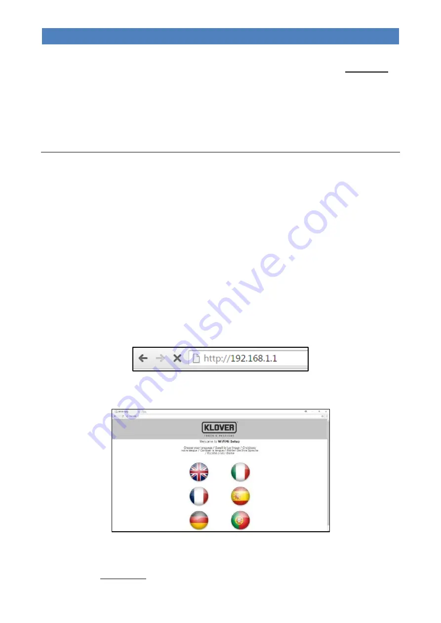
Open the browser on the device you are using (Internet Explorer, Firefox, Safari, etc.) and write the following address 
in the address bar: http://192.168.1.1 . 


5.


This will open the main page of the WiFi module (Welcome to WiFiMi Setup). Select the language you wish to use for 

the subsequent WiFi module configuration menus.  


6.


A new page will open (Welcome to WiFiMi Setup), which will show the details of the previous configuration. If you 

wish to reconnect the module to the network shown, go into “Menu 08 – WIFI STATUS” on the remote control, select 

“RESET”

 and wait for 

“WIFI STATUS”

 to show the value “08” (Module connected). If you wish to connect to a new 

network, press "Search for WiFi networks".  

Summary of Contents for AURA 120

Page 1: ...ENGLISH AURA 80 CLASS 90 AURA 120 REA 100 pellet burning stove INSTALLATION USE MAINTENANCE AND HELPFUL TIPS...

Page 2: ......

Page 3: ...85 PERFORMANCE FEATURES PERFORMANCE Fire resistance A1 Distance from combustible material 200 mm Fuel spillage risk Compliant Emission of combustion products Nominal power Reduced power CO at 13 of O2...

Page 4: ...RES PERFORMANCE Fire resistance A1 Distance from combustible material 200 mm Fuel spillage risk Compliant Emission of combustion products Nominal power Reduced power CO at 13 of O2 0 008 CO at 13 of O...

Page 5: ...PERFORMANCE Fire resistance A1 Distance from combustible material 200 mm Fuel spillage risk Compliant Emission of combustion products Nominal power Reduced power CO at 13 of O2 0 010 CO at 13 of O2 0...

Page 6: ...LLATION 17 POSITIONING 17 SPACES AROUND AND ABOVE THE APPLIANCE 18 EXTERNAL AIR INTAKE 18 THE FLUE AND CONNECTION TO THE SAME 19 CHIMNEY 20 ELECTRICAL CONNECTION 21 CONNECTION TO THE ROOM THERMOSTAT O...

Page 7: ...sfied with this product Please carefully read the warranty certificate on the last page of this User guide The manual contains a detailed description of the appliance and its operation instructions fo...

Page 8: ...he use of poor quality pellets or any other material can damage the appliance operation voiding the warranty and exempting the manufacturer from all liability Do not use the appliance as an incinerato...

Page 9: ...NS SET OUT IN THE SPECIFIC LAWS IN FORCE IN THE COUNTRY WHERE THE MACHINE IS INSTALLED MUST BE OBSERVED NON ROUTINE MAINTENANCE MUST ONLY BE PERFORMED BY AUTHORISED AND QUALIFIED STAFF To ensure the v...

Page 10: ...roswitch for closing tank cover Anti interference filter Main switch connection for power supply cable with 2 built in fuses 4A 250V Flue gas outlet Intake pipe Support panel Wi Fi information Mac add...

Page 11: ...6 AURA 80 CLASS 90 AURA 120 REA 100 PELLET BURNING STOVE EN Rev 1 6 Overall dimensions AURA 80...

Page 12: ...7 AURA 80 CLASS 90 AURA 120 REA 100 PELLET BURNING STOVE EN Rev 1 6 Overall dimensions CLASS 90...

Page 13: ...8 AURA 80 CLASS 90 AURA 120 REA 100 PELLET BURNING STOVE EN Rev 1 6 Overall dimensions AURA 120...

Page 14: ...9 AURA 80 CLASS 90 AURA 120 REA 100 PELLET BURNING STOVE EN Rev 1 6 Overall dimensions REA 100...

Page 15: ...REA 100 PELLET BURNING STOVE EN Rev 1 6 Connections data sheet AURA 80 Description of connections C Ducted air outlet MULTI AIR model only 80 mm M A Intake pipe 50 mm S Flue gas outlet 80 mm M E Elec...

Page 16: ...REA 100 PELLET BURNING STOVE EN Rev 1 6 Connections data sheet CLASS 90 Description of connections C Ducted air outlet MULTI AIR model only 80 mm M A Intake pipe 50 mm S Flue gas outlet 80 mm M E Elec...

Page 17: ...STOVE EN Rev 1 6 Connections data sheet AURA 120 Description of connections C1 Ducted air outlet 1 MULTI AIR model only 80 mm M C2 Ducted air outlet 2 MULTI AIR model only 80 mm M A Intake pipe 50 mm...

Page 18: ...REA 100 PELLET BURNING STOVE EN Rev 1 6 Connections data sheet REA 100 Description of connections A Intake pipe 50 mm Sb Rear Flue gas outlet 80 mm M Su Upper Flue gas outlet 80 mm F E Electricity co...

Page 19: ...meter mm 80 Air intake pipe diameter mm 50 Minimum chimney draught at nominal thermal power Pa 10 Minimum chimney draught at reduced thermal power Pa 10 Combustion gas mass at nominal thermal power g...

Page 20: ...nal frequency Hz 50 Flue outlet diameter mm 80 Air intake pipe diameter mm 50 Minimum chimney draught at nominal thermal power Pa 10 5 Minimum chimney draught at reduced thermal power Pa 10 Combustion...

Page 21: ...bustion gas mass at reduced thermal power g s 3 4 Ventilated pellet tank capacity ducted kg 20 16 Average exhaust flue gas temperature at nominal thermal power C 119 7 Average exhaust flue gas tempera...

Page 22: ...HE PLACE OF INSTALLATION Positioning The initial phase for best installation of the appliance is to determine its optimum location the following elements need to be considered The possibility of creat...

Page 23: ...all behind the appliance is on the outside we recommend you make the hole near it at about 20 cm above the ground see example in Fig A If it is not possible to put an air vent in the wall behind the a...

Page 24: ...free and independent internal cross section Rectangular cross sections must have a maximum ratio of 1 5 between the sides If the flue is installed externally it must be insulated in order to prevent...

Page 25: ...duct the flue using a stainless steel pipe properly insulated with rock wool or vermiculite and sized according to the route The connection to the flue must be appropriately sealed When assembling the...

Page 26: ...e s safety is ensured when it is properly connected to an efficient earthing system In the electric connection to the mains power supply include a 6 A Id 30 mA differential trip switch with suitable b...

Page 27: ...thermostats are satisfied Ducted fan 1 will switch to modulation mode in any case With Room sensor Pr56 must be enabled with value S1 or S1 2 Once the SET ROOM 1 temperature setting is reached Menu 12...

Page 28: ...of the selected menu item Decreases the room temperature setting operating power In SET DUCTING mode it modifies the value of ducting 1 3 ON OFF On the first press Activates the display Working Switc...

Page 29: ...Ds on the support panel work LED Description Status Action 1 ON OFF Off The appliance is off Flashing The appliance is shutting down On The appliance is on 2 and 3 POWER STATUS Led 2 On Led 3 Off Powe...

Page 30: ...ettings 1 3 or 5 With the help of LEDs 2 and 3 Power status you can check the set power setting see LED table Display The remote control display shows information concerning the operating status of th...

Page 31: ...nce once the SET ROOM temperature setting has been reached is excluded The operating power will however be modulated the display will show the word MODULATION If enabled the appliance will enter modul...

Page 32: ...d 2 Increase and Decrease allow you to modify the selected value Key 4 Set selects the subsequent value Key 5 Esc selects the previous value Key 3 ON OFF takes you back to the previous menu item Numbe...

Page 33: ...the screen display for the enabling days Key 1 Increase enables the selected day Key 2 Decrease disables the selected day Key 4 Set selects the subsequent day Key 5 Esc selects the previous day Key 3...

Page 34: ...selects the subsequent value Key 5 Esc selects the previous value Key 3 ON OFF takes you back to the previous menu item Menu 04 Language Allows you to select the dialogue language from the available...

Page 35: ...low shows the various devices and their meanings Display Meaning L04 270218 example Firmware code loaded in the control unit ARIA 1 0 example Firmware code loaded in the remote control F GS T Indicate...

Page 36: ...en for the WiFi card The table below shows the various items and their meanings Display Meaning Values displayed SIGNAL Indicates the value of the Wifi signal detected by the reception card 0 100 CHAN...

Page 37: ...sonal injuries Menu 11 Relax function Menu not available Allows for reducing the front air fan speed for a pre set time 90 min Menu 12 Set Room Duc Menu displayed only on models with this function All...

Page 38: ...chapter 1 Power the appliance using the main ON OFF switch on the rear of the appliance 2 Check that in Menu 08 WIFI STATUS on the remote control that the item WIFI STATUS shows a value of 02 Access...

Page 39: ...to connect the appliance to the Internet from the list and enter the password for the selected network If the network is hidden click on the item Custom SSID and enter the required parameters 8 Click...

Page 40: ...ng registration You can now enter a new device by clicking on Add stove in the main menu During this procedure you will need the ITEM CODE Model and SERIAL NUMBER for your appliance shown on the CE la...

Page 41: ...STABILISATION Flame stabilisation allowing uniform ignition of all pellets unburnt during the previous stages Approx 8 minutes At the end of the ignition cycle the appliance switches to working mode...

Page 42: ...s between 07 C and 40 C can be set Pressing key 3 On Off or waiting a few seconds without confirming will mean that the set value is not saved During this operation the display will appear as in the f...

Page 43: ...e to modify the value for the ducted air fan for zone 2 and confirm by pressing key 4 Set or 5 Esc the value can be set manually from 1 to 5 or set to automatic A connected with the value set in SET P...

Page 44: ...check the seal on the flue gas pipes and the filter of the ash vacuum device used for cleaning What happens if the pellets do not ignite If the ignition fails the display will show the alarm message I...

Page 45: ...s occurs when the encoder tachometer in the extractor detects an extractor speed equal to 0 AL 05 IGNIT FAILED No ignition This occurs when the minimum temperature in the combustion chamber Pr13 is no...

Page 46: ...irective 89 391 EEC The required cleaning frequency depends on the type and quality of the pellets used The schedule indicated below may therefore vary Any problem affecting the appliance caused by la...

Page 47: ...anger cleaning hook to lift the rod and move it backwards and forwards to clean the air heat exchanger of combustion residues figure 3 Empty the ash drawer Figure 4 The ash tray on AURA 120 and REA 10...

Page 48: ...gure 7 WARNING use suitable ash vacuum devices equipped with a fine mesh filter in order to prevent ash from being blown into the room and to prevent damaging the vacuum cleaner We do not recommend th...

Page 49: ...8 After having removed the two inspection plates in the picture figure 9 clean the right and left flue gas conduits with a brush figure 10 Remove the front panel below To remove it unscrew both screws...

Page 50: ...ction vent unscrewing the two screws figure 14 After having removed the vent vacuum the residues inside the compartment figure 15 To ensure correct operation it is necessary to remove the sawdust depo...

Page 51: ...nning of winter and whenever it becomes necessary It is important to check for any obstructions in the flue before switching the appliance on following long periods of inactivity If the flue is not cl...

Page 52: ...d ducting 1 in power 4 work phase SPE DUC 1 P 4 Volt 65 225 65 Pr61 M10 03 07 Heat exchanger 2 speed ducting 1 in power 5 work phase SPE DUC 1 P 5 Volt 65 225 65 Pr62 M10 03 08 Heat exchanger 3 speed...

Page 53: ...hase SPE FLUE GAS P 1 RPM 500 2800 1500 Pr19 M10 05 19 Flue gas extraction speed in power 2 work phase SPE FLUE GAS P 2 RPM 500 2800 1650 Pr20 M10 05 20 Flue gas extraction speed in power 3 work phase...

Page 54: ...Heat exchanger 3 speed ducting 2 in power 4 work phase SPE DUC 2 P 4 Volt 65 225 65 Pr66 M10 03 12 Heat exchanger 3 speed ducting 2 in power 5 work phase SPE DUC 2 P 5 Volt 65 225 65 Parameters VARIOU...

Page 55: ...10 05 21 Flue gas extraction speed in power 4 work phase SPE FLUE GAS P 4 RPM 500 2800 1900 Pr22 M10 05 22 Flue gas extraction speed in power 5 work phase SPE FLUE GAS P 5 RPM 500 2800 2100 Pr23 M10 0...

Page 56: ...speed ducting 2 in power 4 work phase SPE DUC 2 P 4 Volt 65 225 65 Pr66 M10 03 12 Heat exchanger 3 speed ducting 2 in power 5 work phase SPE DUC 2 P 5 Volt 65 225 65 Parameters VARIOUS CALIBRATIONS M...

Page 57: ...1 M10 05 21 Flue gas extraction speed in power 4 work phase SPE FLUE GAS P 4 RPM 500 2800 2250 Pr22 M10 05 22 Flue gas extraction speed in power 5 work phase SPE FLUE GAS P 5 RPM 500 2800 2400 Pr23 M1...

Page 58: ...hanger 3 speed ducting 2 in power 4 work phase SPE DUC 2 P 4 Volt 65 225 220 Pr66 M10 03 12 Heat exchanger 3 speed ducting 2 in power 5 work phase SPE DUC 2 P 5 Volt 65 225 225 Parameters VARIOUS CALI...

Page 59: ...M10 05 21 Flue gas extraction speed in power 4 work phase SPE FLUE GAS P 4 RPM 500 2800 2250 Pr22 M10 05 22 Flue gas extraction speed in power 5 work phase SPE FLUE GAS P 5 RPM 500 2800 2400 Pr23 M10...

Page 60: ...speed ducting 2 in power 4 work phase SPE DUC 2 P 4 Volt 65 225 65 Pr66 M10 03 12 Heat exchanger 3 speed ducting 2 in power 5 work phase SPE DUC 2 P 5 Volt 65 225 65 Parameters VARIOUS CALIBRATIONS Mo...

Page 61: ...1 M10 05 21 Flue gas extraction speed in power 4 work phase SPE FLUE GAS P 4 RPM 500 2800 2150 Pr22 M10 05 22 Flue gas extraction speed in power 5 work phase SPE FLUE GAS P 5 RPM 500 2800 2300 Pr23 M1...

Page 62: ...57 AURA 80 CLASS 90 AURA 120 REA 100 PELLET BURNING STOVE EN Rev 1 6 WIRING DIAGRAM...

Page 63: ...r it The Klover Warranty will remain in effect for a period of 2 years from the date of purchase if proven by a delivery note or other proof of purchase e g receipt stating the name of the seller the...

Page 64: ...ated to improper functioning of the chimney flue Defects in the Product caused by negligence accidental breakage normal wear and tear tampering and or damage during transport scratches dents etc inclu...

Page 65: ...60 AURA 80 CLASS 90 AURA 120 REA 100 PELLET BURNING STOVE EN Rev 1 6...

Page 66: ...61 AURA 80 CLASS 90 AURA 120 REA 100 PELLET BURNING STOVE EN Rev 1 6...

Page 67: ...62 AURA 80 CLASS 90 AURA 120 REA 100 PELLET BURNING STOVE EN Rev 1 6...

Page 68: ...Cod CS IST A80 EN KLOVER Srl Via A Volta 8 37047 San Bonifacio VR VAT No 02324280235 www klover it...

Reviews: