120
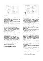
Procedure
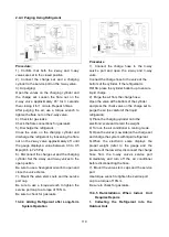
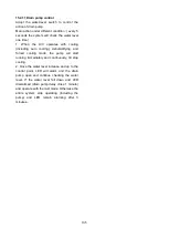
1). Confirm that both the 2-way and 3-way
valves are open.
Remove the valve stem caps and confirm that
the valve stems are open.
Be sure to use a hexagonal wrench to operate
the valve stems.
2). Connect the charge hose with the push pin
of handle lo to the 3-way valves gas service
port.
3). Purge the air from the charge hose.
Open the handle Lo valve of the manifold valve
slightly to purge air from the charge hose for 5
seconds and then close it quickly.
4). Close the 2-way valve.
5). Turn on the air conditioner in cooling mode.
Turn it off when the gauge indicates
-0.1MPa(14.5Psi).
6).Immediately close the 3-way valve
Do this quickly so that the gauge displays a
value between 0.3 to 0.5 Mpa(43.5 to 72.5Psi).
Disconnect the charge set, and tighten the
2-way and 3-way valves’ stem nuts.
Use a torque wrench to tighten the 3-way valves
service port cap to a torque of 18N.m.
Be sure to check for gas leaks.
2. Air Purging by the Refrigerant
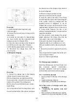
Procedure:
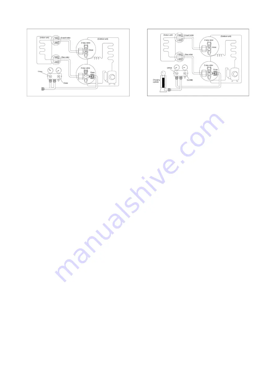
1). Confirm that both the 2-way and 3-way
valves are closed.
2). Connect the charge set and a charging
cylinder to the service port of the 3-way valve
Leave the valve on the charging cylinder closed.
3). Purge the air from the charge hose.
Open the valves on the charging cylinder and
the charge set. Purge the air by loosening the
flare nut on the 2-way valve approximately 45’
for 3 seconds and then closing it for 1 minute.
Repeat 3 times.
After purging the air, use a torque wrench to
tighten the flare nut on the 2-way valve.
4). Check for gas leaks
Check the flare connections for gas leakage.
5). Discharge the refrigerant.
Close the valve on the charging cylinder and
discharge the refrigerant by loosening the flare
nut on the 2-way valve approximately 45’ until
the gauge indicates 0.3 to 0.5 Mpa(43.5 to
72.5Psi)
6). Disconnect the charge set and the charging
cylinder, and open the 2-way and 3-way valves
Be sure to use a hexagonal wrench to operate
the valve stems.
7). Mount the valve stems nuts and the service
port cap.
Be sure to use a torque wrench to tighten the
service port cap to a torque 18N.m.
Be sure to check for gas leakage.
13.4.6 Re-Installation When the Outdoor
Unit Requires Repairs
1. Evacuation for
the whole system
Summary of Contents for KDIP012-H2
Page 8: ...5 2 2 Part names of Indoor Outdoor units Cassette Units ...
Page 9: ...6 KDIR Duct Units ...
Page 10: ...7 KDIP Duct Units ...
Page 11: ...9 Ceiling floor Units ...
Page 12: ...10 HESP DUCT Units ...
Page 19: ...19 2 3 4 7 Outside Water Pump for Optional When Ceiling Installation ...
Page 31: ...33 KSIE024 H220 O KSIR036 H218 inch 37 2 16 1 31 9 40 6 26 5 15 9 ...
Page 34: ...36 Ceiling floor Units ...
Page 39: ...41 KTIR036 H2G1 KTIR048 H2G1 ...
Page 40: ...43 KUIR18 H2 KUIR24 H2 ...
Page 41: ...44 KFUF036 H2G1 KFUF048 H2G1 ...
Page 42: ...45 KFUF060 H2G1 ...
Page 43: ...46 KFUF036 H2G1 KFUF048 H2G1 ...
Page 44: ...47 KDIP090 H2 KDIP012 H2 KDIP018 H2 KDIP24 H2 ...
Page 69: ...74 6 2 Outdoor Unit KSIE018 H220 O KSIE024 H220 O ...
Page 70: ...75 KSIE009 H221 O KSIE012 H220 O ...
Page 71: ...77 KSIR036 H218 ...
Page 77: ...83 KDIR09 H2 Code 0 Code 1 Code 2 Code 3 Code 4 ...
Page 78: ...84 KDIR12 H2 Code 0 Code 1 Code 2 Code 3 Code 4 ...
Page 79: ...85 KDIR18 H2 Code 0 Code 1 Code 2 Code 3 Code 4 ...
Page 80: ...86 KDIR24 H2 Code 0 Code 1 Code 2 Code 3 Code 4 ...
Page 96: ...104 12 Field Wiring 9K 24K 36K 48K 60K ...
Page 97: ...105 ...
Page 147: ...155 P U P V ...
Page 148: ...156 P W P N ...
Page 181: ...191 4 Remove the evaporator fixing clamps to disassemble the evaporator Fixing clamps 1 screw ...
Page 188: ...221 5 Remove the four fixing screws of the fan motor then remove the motor 5 ...


